设计简介
摘 要
模具制造技术迅速发展,已成为现代制造技术的重要组成部分。如模具的CAD/CAM技术,模具的激光快速成型技术,模具的精密成形技术,模具的超精密加工技术。
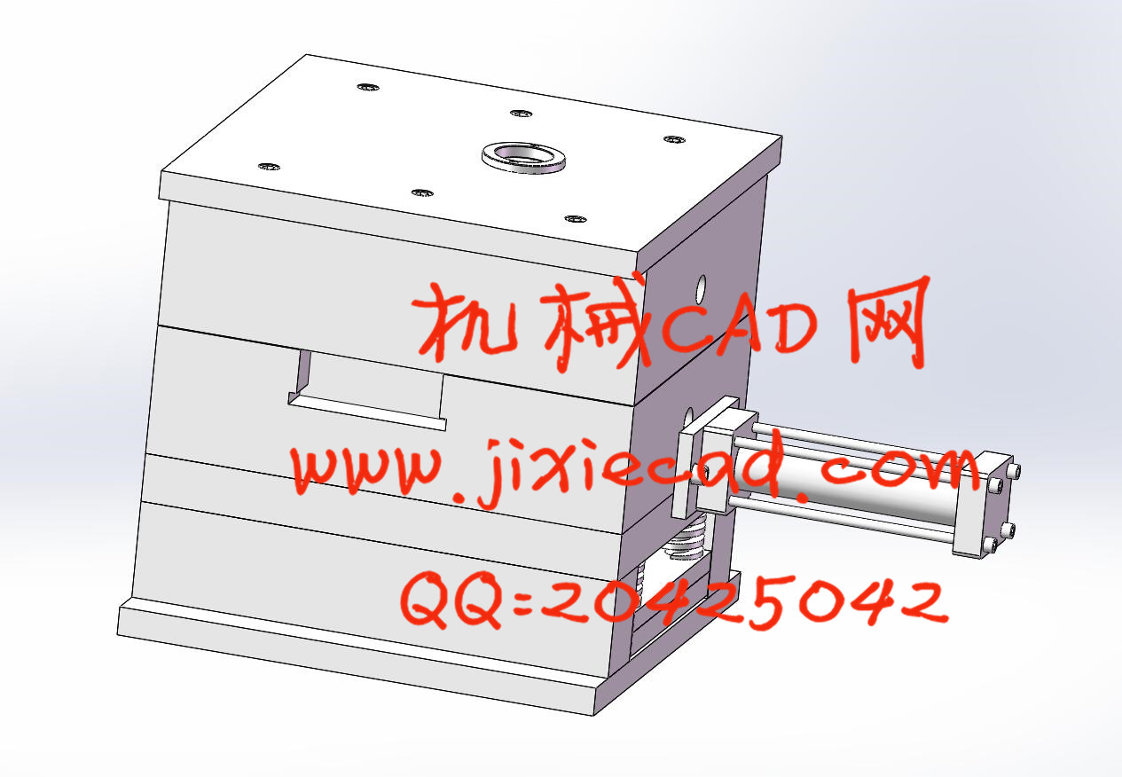
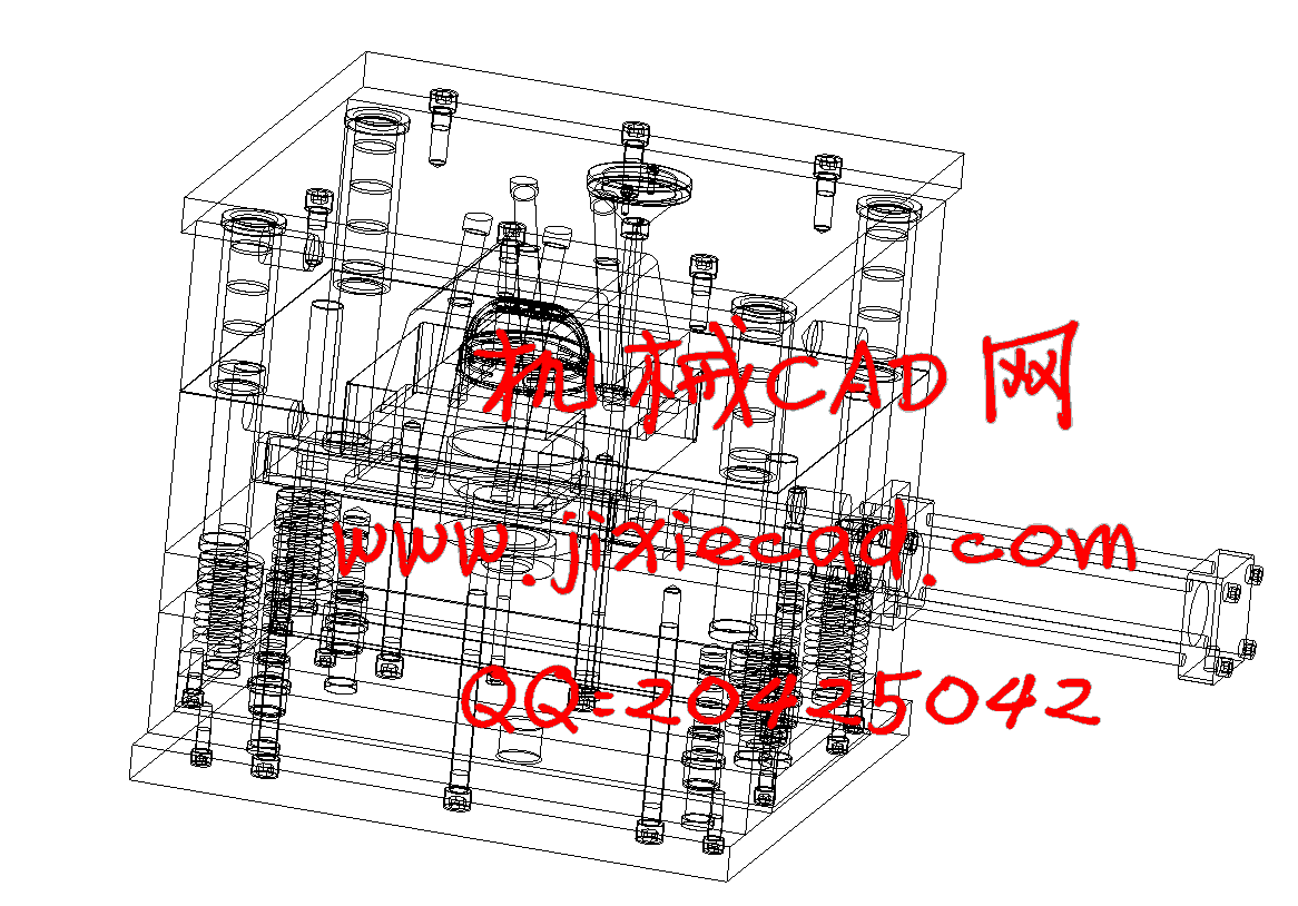
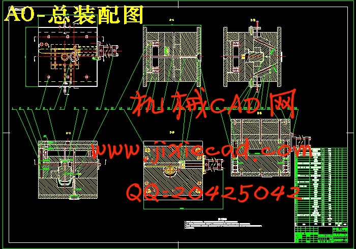
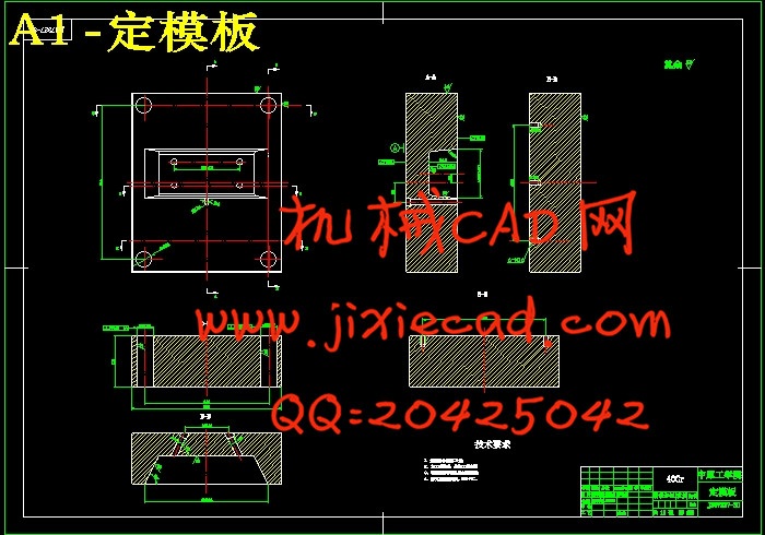
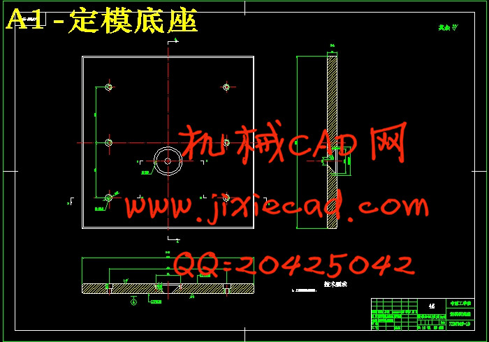
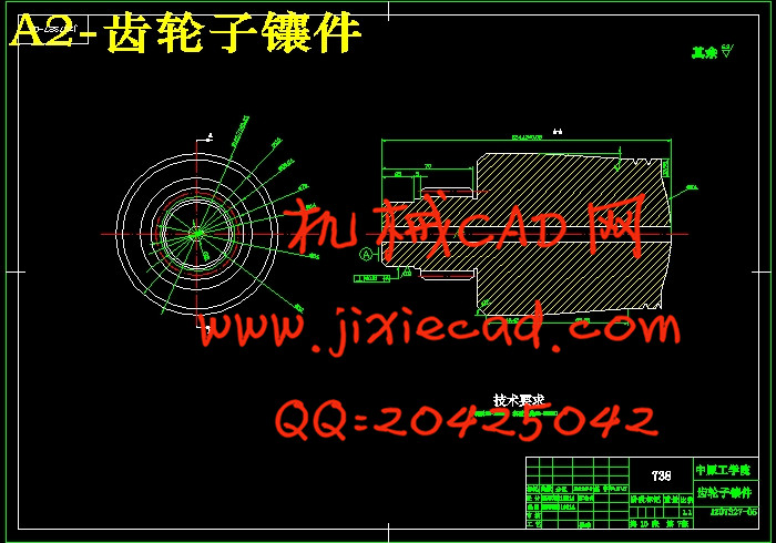
本设计介绍了该注塑模具的设计与制造方法。该注射模采用了一模一腔的结构,其中的设计内容有塑件的工艺性分析、塑件的体积和质量计算及注射机参数的确定;结构设计:分型面选择、型腔数确定、型腔的排列方式、浇口设计、侧向分型抽芯机构设计、推出及复位机构方式确定;型芯、型腔尺寸计算;模具加热和冷却系统计算;模具闭合高度确定;注射机有关参数的校核;如此设计出的结构可确保模具工作运用可靠。最后对模具结构与注射机的匹配进行了校核。并用autoCAD绘制了一套模具装配图和零件图。
关键词:塑料 注射模具 侧向抽芯
Abstract
The die making technology rapidly expand, has become the modern technique of manufacture the important component. For example, mold's CAD/CAM technology, mold's laser fast formation technology, mold's precise form technology, mold's ultra precision sizing technology.
This design introduced the injected mold's design and the manufacture method. This injection mold has used 1 mold 1 cavity structures. which is designed as part of the craft-oriented establishment : Plastic Parts of the Process Analysis, Plastic Parts of the size and quality of calculation and the injection parameters set; Structural design : Surface choice cavity determination, Cavity the arrangement, gate design, lateral type pulling mechanism design, launch and reattached body identified; Core, Cavity size calculation; Die heating and cooling system computation; Mold closing high set; Injection machine parameters in the verification; The design of such a structure can be used to ensure reliable die. Finally, the injection mold structure and the matching machine was calibrated. Using a set of auto mapping mold parts and assembly plans.
Key word: Plastic injection mold side core
目录
1 引言……………………………………………………………………………(1)
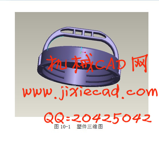
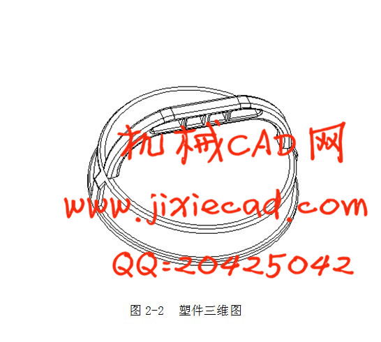
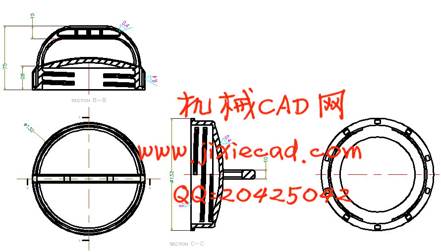
2 注塑件的分析…………………………………………………………………(2)
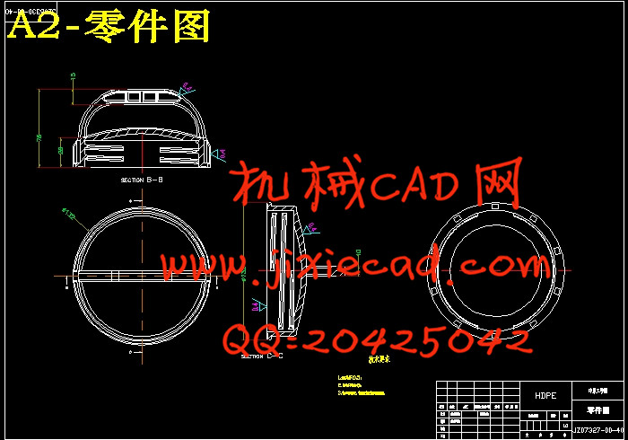
2.1注塑件零件图……………………………………………………………(2)
2.2 HDPE塑料概述 …………………………………………………………(2)
2.3 HDPE收缩率的确定 ……………………………………………………(3)
2.4 塑件的尺寸精度及表面质量……………………………………………(4)
2.5塑结构分析 ……………………………………………………………(5)
3 注塑成型参数确定……………………………………………………………(6)
3.1 注塑成型的工艺参数……………………………………………………(6)
3.2 注塑机的选择……………………………………………………………(7)
3.3 模具在注塑机上的安装尺寸校核………………………………………(8)
4 分型面的确定及行腔数目的定………………………………………………(10)
4.1 分型面的确定…………………………………………………………(10)
4.1.1分型面的选择原则………………………………………………(10)
4.1.2分型面的形式……………………………………………………(11)
4.1.3分型面的设计……………………………………………………(11)
4.2行腔数目的确定…………………………………………………………(11)
4.2.1初步确定行腔数目………………………………………………(11)
4.2.2根据最大注塑量确定行腔数目…………………………………(12)
5 浇注系统的设计………………………………………………………………(13)
5.1交流道设计………………………………………………………………(13)
5.2分流道的设计……………………………………………………………(14)
5.3浇口设计…………………………………………………………………(14)
5.4冷料穴的设计……………………………………………………………(15)
6 模具材料的选择及模架的确定………………………………………………(16)
6.1模具材料的选择…………………………………………………………(16)
6.2模架的确定………………………………………………………………(17)
6.2.1模架的确定………………………………………………………(17)
6.2.2模架的选用………………………………………………………(18)
7 确定主要零件结构设计………………………………………………………(19)
7.1成型零件工作尺寸计算…………………………………………………(19)
7.1.1成型零件尺寸计算的基本内容…………………………………(20)
7.1.2行腔、型芯工作尺寸计算…………………………………………(20)
7.2斜导柱抽芯机构设计……………………………………………………(21)
7.2.1斜导柱的设计……………………………………………………(21)
7.2.2滑块的组合形式…………………………………………………(22)
7.2.3各项尺寸计算与校核……………………………………………(22)
7.3脱模机构设计……………………………………………………………(22)
7.4导向机构的设计…………………………………………………………(23)
7.4.1导柱的设计………………………………………………………(24)
7.4.2导套的设计………………………………………………………(24)
7.5顶出机构的设计…………………………………………………………(24)
8 冷却系统的设计………………………………………………………………(24)
8.1 温度调节对塑件的影响………………………………………………(24)
8.2 对温度调节系统要求…………………………………………………(25)
8.3 冷却系统的设计………………………………………………………(25)
9 模具排气槽的设计……………………………………………………………(26)
10 proe参数化设计……………………………………………………………(26)
11 绪论…………………………………………………………………………(28)
12 参考文献……………………………………………………………………(29)
13 致谢…………………………………………………………………………(30)
模具制造技术迅速发展,已成为现代制造技术的重要组成部分。如模具的CAD/CAM技术,模具的激光快速成型技术,模具的精密成形技术,模具的超精密加工技术。
本设计介绍了该注塑模具的设计与制造方法。该注射模采用了一模一腔的结构,其中的设计内容有塑件的工艺性分析、塑件的体积和质量计算及注射机参数的确定;结构设计:分型面选择、型腔数确定、型腔的排列方式、浇口设计、侧向分型抽芯机构设计、推出及复位机构方式确定;型芯、型腔尺寸计算;模具加热和冷却系统计算;模具闭合高度确定;注射机有关参数的校核;如此设计出的结构可确保模具工作运用可靠。最后对模具结构与注射机的匹配进行了校核。并用autoCAD绘制了一套模具装配图和零件图。
关键词:塑料 注射模具 侧向抽芯
Abstract
The die making technology rapidly expand, has become the modern technique of manufacture the important component. For example, mold's CAD/CAM technology, mold's laser fast formation technology, mold's precise form technology, mold's ultra precision sizing technology.
This design introduced the injected mold's design and the manufacture method. This injection mold has used 1 mold 1 cavity structures. which is designed as part of the craft-oriented establishment : Plastic Parts of the Process Analysis, Plastic Parts of the size and quality of calculation and the injection parameters set; Structural design : Surface choice cavity determination, Cavity the arrangement, gate design, lateral type pulling mechanism design, launch and reattached body identified; Core, Cavity size calculation; Die heating and cooling system computation; Mold closing high set; Injection machine parameters in the verification; The design of such a structure can be used to ensure reliable die. Finally, the injection mold structure and the matching machine was calibrated. Using a set of auto mapping mold parts and assembly plans.
Key word: Plastic injection mold side core
目录
1 引言……………………………………………………………………………(1)
2 注塑件的分析…………………………………………………………………(2)
2.1注塑件零件图……………………………………………………………(2)
2.2 HDPE塑料概述 …………………………………………………………(2)
2.3 HDPE收缩率的确定 ……………………………………………………(3)
2.4 塑件的尺寸精度及表面质量……………………………………………(4)
2.5塑结构分析 ……………………………………………………………(5)
3 注塑成型参数确定……………………………………………………………(6)
3.1 注塑成型的工艺参数……………………………………………………(6)
3.2 注塑机的选择……………………………………………………………(7)
3.3 模具在注塑机上的安装尺寸校核………………………………………(8)
4 分型面的确定及行腔数目的定………………………………………………(10)
4.1 分型面的确定…………………………………………………………(10)
4.1.1分型面的选择原则………………………………………………(10)
4.1.2分型面的形式……………………………………………………(11)
4.1.3分型面的设计……………………………………………………(11)
4.2行腔数目的确定…………………………………………………………(11)
4.2.1初步确定行腔数目………………………………………………(11)
4.2.2根据最大注塑量确定行腔数目…………………………………(12)
5 浇注系统的设计………………………………………………………………(13)
5.1交流道设计………………………………………………………………(13)
5.2分流道的设计……………………………………………………………(14)
5.3浇口设计…………………………………………………………………(14)
5.4冷料穴的设计……………………………………………………………(15)
6 模具材料的选择及模架的确定………………………………………………(16)
6.1模具材料的选择…………………………………………………………(16)
6.2模架的确定………………………………………………………………(17)
6.2.1模架的确定………………………………………………………(17)
6.2.2模架的选用………………………………………………………(18)
7 确定主要零件结构设计………………………………………………………(19)
7.1成型零件工作尺寸计算…………………………………………………(19)
7.1.1成型零件尺寸计算的基本内容…………………………………(20)
7.1.2行腔、型芯工作尺寸计算…………………………………………(20)
7.2斜导柱抽芯机构设计……………………………………………………(21)
7.2.1斜导柱的设计……………………………………………………(21)
7.2.2滑块的组合形式…………………………………………………(22)
7.2.3各项尺寸计算与校核……………………………………………(22)
7.3脱模机构设计……………………………………………………………(22)
7.4导向机构的设计…………………………………………………………(23)
7.4.1导柱的设计………………………………………………………(24)
7.4.2导套的设计………………………………………………………(24)
7.5顶出机构的设计…………………………………………………………(24)
8 冷却系统的设计………………………………………………………………(24)
8.1 温度调节对塑件的影响………………………………………………(24)
8.2 对温度调节系统要求…………………………………………………(25)
8.3 冷却系统的设计………………………………………………………(25)
9 模具排气槽的设计……………………………………………………………(26)
10 proe参数化设计……………………………………………………………(26)
11 绪论…………………………………………………………………………(28)
12 参考文献……………………………………………………………………(29)
13 致谢…………………………………………………………………………(30)