设计简介
摘要
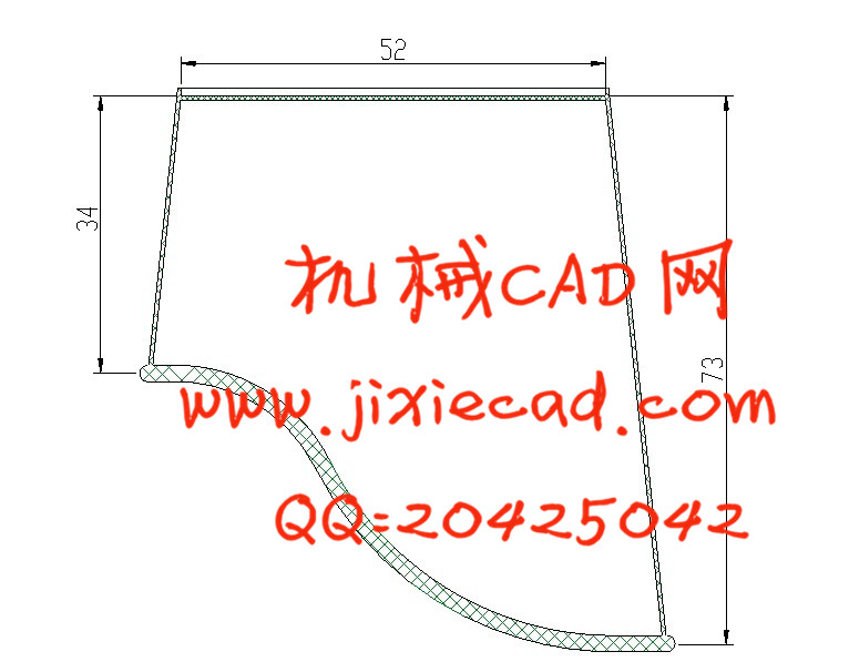
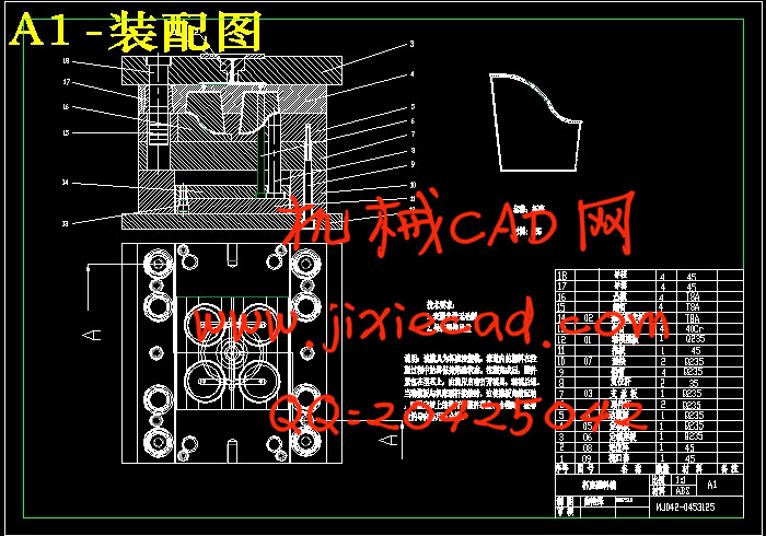
本设计题目为杯座注塑模设计,体现了深薄壁类塑料零件的设计要求、内容及方向,有一定的设计意义。通过对该零件模具的设计,进一步加强了设计者注塑模设计的基础知识,为设计更复杂的注塑模具做好了铺垫和吸取了更深刻的经验。本设计运用塑料成型工艺及模具设计的基础知识,首先分析了塑件的成分及性能要求,为选取浇口的类型做好了准备;然后估算了塑件的体积,便于选取注塑机及确定型腔数量;最后分析了塑件的特征,确定模具的设计参数、设计要点及推出装置的选取。
本副模具的设计中,在顶管的尾部安装了推力轴承,在上升的过程中,塑件及推块同时发生转动,直到塑件脱出型腔。这种机构脱模可靠,设计方便且在模具中占用空间较小,非常适合在本副模具中使用。
关键词:注塑模 浇口 型腔
Abstract
The requirement ,content and direction of the design of the deep thin wall plastic parts are embodied on this injection mould design of the plastic parts of long pipe box. The designer’s foundation knowledge of the injection mould design is reinforced and is able to design more complex injection mould through the design.
Through the foundation knowledge, firstly, the composion and the perfourmance of thr part is analyzed to choose the type of the gat advantagely. Secondly, the volume of the part is estimated to choose the injection molding machine and to detemine the mould quantity conveniencely. Lastly the character of the part is analyzed to determine the mould design parameter and design point and choose the ejection assembly. The part’s outside gear has gullets that are inconsistent with the open direction of the mould. Inaddition, a helical angle exists between them. So the devece that drives the part and the mould to ratat simutaneously when the mould is opend is be designed necessarily. In this mould design, the thrust bearing is fixed at the end of thr conduit block to make ejecting block that rotats with the part at the same time untile the part is ejected from the mould upward. The device makes ejection credibly and design conveniencly and occupies lettle room. So, it is adapted to be used on this mould extraordinarily.
Keywords: Injection mould , gate , Cavity
杯 座 模 具 设 计
目录
摘要 3绪论 4
第1章 设计题目:杯座模具设计 8
第2章 工艺性分析 12
2.1 塑料的原材料(ABS)分析 12
2.2 塑件的结构和尺寸精度等级及表面质量分析 12
2.3 计算塑料制件的体积和质量 13
2.4 塑件注塑工艺参数的确定 14
第3章 注塑模具的结构设计 15
3.1 模腔数量的确定 15
3.1.1 按注射机的额定锁模力确定型腔数量N1 15
3.1.2 注射机注塑量确定型腔数目N2 16
3.2 分型面的选择以及型腔的排列方式的确定 16
3.2.1 分型面的选择 17
3.2.2 确定型腔的排列方式 17
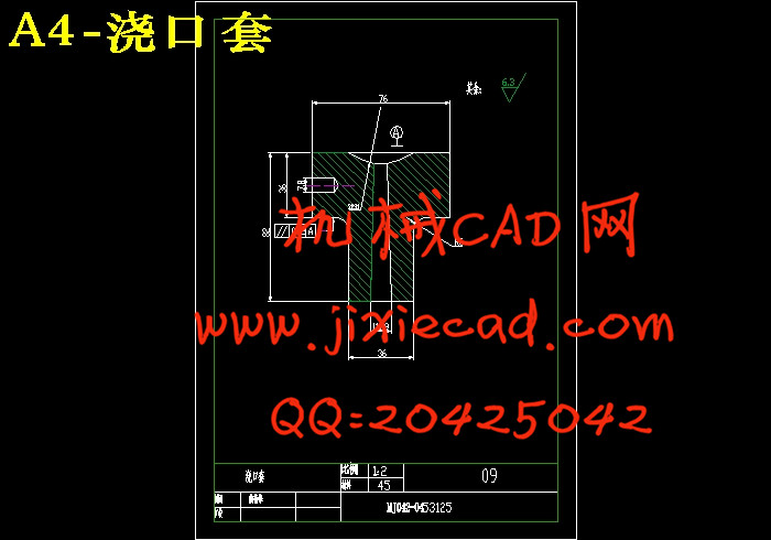
3.3 浇注系统形式和浇口的设计 18
3.4 排气结构的设计 20
3.5成型零件设计 20
第4章模具设计的有关计算 22
4.1型腔、型芯工作尺寸计算 22
4.2型腔侧壁厚度和底板厚度计算 23
4.3模具加热与冷却系统的计算 23
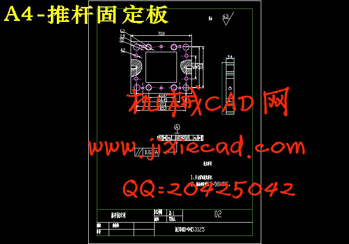
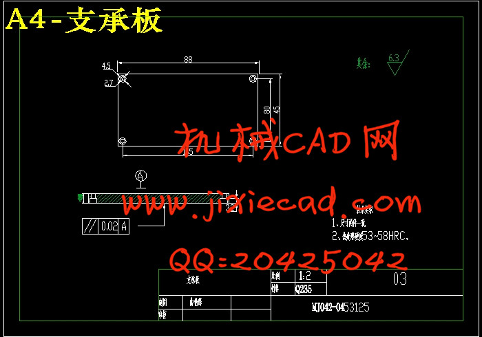
4.4 结构与辅助零部件的设计 24
4.5 模具闭合高度的确定 25
4.6注塑机有关参数的校核 25
第5章 塑料模的装配、试模与维修 27
5.1模具装配 27
5.2试模 27
5.3 试模可能产生的问题及改善措施 28
5.3.1 粘着模腔 28
5.3.2 粘着模芯 28
5.3.3 粘着主流道 29
5.3.4 成型缺陷 29
5.3.5 调整措施 30
第6章 绘制模具总装图 31
第7章 机械加工工艺过程卡 32
第8章 用Pro/E画图的过程 36
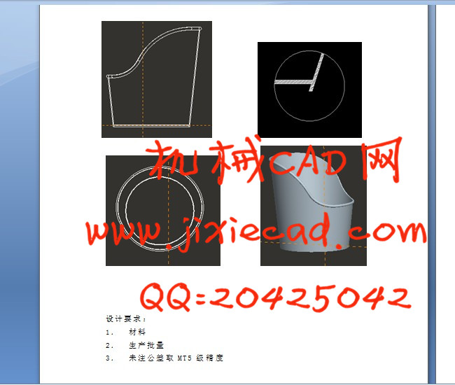
8.1用Pro-E画杯座零件的过程 36
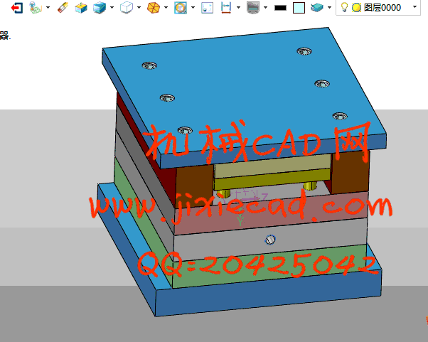
8.2用Pro-E画杯座模具的过程 36
8.2.1:加载参照模型 36
8.2.2:成型零件设计 36
8.2.3:浇注系统设计及开模 36
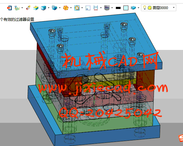
8.2.4:模架及其他模具零件设计 37
8.2.5:模具元件后期处理 37
总结 38
致谢 39
参考文献 40