设计简介
摘要
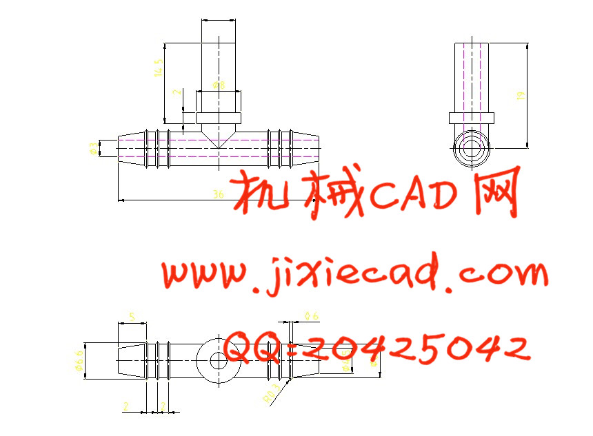
本文讨论了塑料三通注塑模设计过程。介绍了注塑模成型工艺和注塑模具的结构及工作原理。塑料三通采用的是塑料-ABS,热塑性塑料的主要成型工艺是注射成型,因此,塑料三通成型方法采用注塑成型。
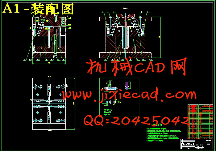
本设计对塑料三通进行了工艺分析,确定了分型面、浇注系统等,选择了注塑机,计算了成型零部件的尺寸。确定了模具浇口、限位装置、顶出机构、导柱和导套,这样设计出的结构可确保模具工作可靠和灵活。最后对注射机进行选择和校核。
本论文基于、CAD系统,通过该系统,用户可以在可视化平台上交互式的设计注塑模具各个部件,不仅可以避免相似零件设计的重复性,大大提高其设计效率和设计质量,缩短产品的开发周期,而且方便了产品后续的有限元分析,同时也符合了现代设计思想的发展要求。
关键词:注塑模 工艺分析 注塑件工艺性 模具浇口 注塑成型
Abstract
本文讨论了塑料三通注塑模设计过程。介绍了注塑模成型工艺和注塑模具的结构及工作原理。塑料三通采用的是塑料-ABS,热塑性塑料的主要成型工艺是注射成型,因此,塑料三通成型方法采用注塑成型。
本设计对塑料三通进行了工艺分析,确定了分型面、浇注系统等,选择了注塑机,计算了成型零部件的尺寸。确定了模具浇口、限位装置、顶出机构、导柱和导套,这样设计出的结构可确保模具工作可靠和灵活。最后对注射机进行选择和校核。
本论文基于、CAD系统,通过该系统,用户可以在可视化平台上交互式的设计注塑模具各个部件,不仅可以避免相似零件设计的重复性,大大提高其设计效率和设计质量,缩短产品的开发周期,而且方便了产品后续的有限元分析,同时也符合了现代设计思想的发展要求。
关键词:注塑模 工艺分析 注塑件工艺性 模具浇口 注塑成型
Abstract
This article discusses the process of plastic injection mold design links. Describes the injection molding process and injection mold structure and working principle. Three plastic used in plastic-ABS, the main molding thermoplastic injection molding process is, therefore, the plastic molding method using cast molding tee.
The design of the plastic tee conducted a process analysis to determine the sub-surface, casting systems, choose the injection molding machine, forming parts of the calculated size. Determine the mold gate, limiter, top of the organization, guide pillars and sets, so the structure can be designed to ensure reliable and flexible molds. Finally, select the injection machine and check.
This paper based on , CAD system, through the system, users can visualize the interactive platform in all parts injection mold design, part design is similar to not only avoid repetitive, greatly improve their design efficiency and design quality, shorten product development cycles, and facilitate follow-up of the finite element analysis of the product, but also in line with the development of modern design requirements.
Key words: Injection Mould Process analysis Injection Molding Process Mold Gate Injection molding
目录
第1章 绪论 1The design of the plastic tee conducted a process analysis to determine the sub-surface, casting systems, choose the injection molding machine, forming parts of the calculated size. Determine the mold gate, limiter, top of the organization, guide pillars and sets, so the structure can be designed to ensure reliable and flexible molds. Finally, select the injection machine and check.
This paper based on , CAD system, through the system, users can visualize the interactive platform in all parts injection mold design, part design is similar to not only avoid repetitive, greatly improve their design efficiency and design quality, shorten product development cycles, and facilitate follow-up of the finite element analysis of the product, but also in line with the development of modern design requirements.
Key words: Injection Mould Process analysis Injection Molding Process Mold Gate Injection molding
目录
1.1 模具工业在国民经济中的地位 1
1.2 各种模具的分类和占有量 2
1.3 我国模具工业的现状 2
1.4 世界五大塑料生产国的产能状况 4
1.5 我国模具技术的现状及发展趋势 6
1.6 毕业设计的主要研究目标及内容 7
1.6.1设计目标 7
1.6.2设计内容 7
1.7 本章小结 8
第2章 注塑件的工艺性 9
2.1 塑件材料工艺性分析 9
2.1.1材料基本特征 11
2.1.2材料主要用途 12
2.1.3材料成型特点 15
2.2 塑料制品的工艺性分析 16
2.2.1收缩性 16
2.2.1.1模具结构设计对塑件收缩的影响 17
2.2.1.2塑件结构设计对塑件收缩的影响 17
2.2.2脱模斜度 18
2.2.3壁厚 18
2.2.4侧孔 19
2.2.5圆角 19
2.2.6塑件的尺寸精度及表面质量 19
2.2.6.1尺寸精度 20
2.2.6.2塑件的表面质量 20
2.3 成型周期 20
2.4 本章小结 21
第3章 注塑成型的准备 22
3.1 注塑成型工艺简介 22
3.2 注塑成型工艺条件 22
3.3 注塑机的选择 24
3.3.1注塑机简介 24
3.3.2注射机基本参数 26
3.3.3选择注塑机 26
3.4 注射机的校核 27
3.4.1最大注射量的校核 27
3.4.2锁模力的校核 27
3.4.3塑化能力的校核 28
3.5 安装部分的尺寸校核 28
3.5.1模具安装尺寸校核 28
3.5.1.1定位圈尺寸校核 28
3.5.1.2模具的长度与宽度校核 28
3.5.1.3模具厚度校核 29
3.5.1.4喷嘴尺寸校核 29
3.6 开模行程校核 29
3.7 本章小结 29
第4章 模具设计 31
4.1 分型面的确定 31
4.2 型腔数目的确定 31
4.3 浇口确定 32
4.4 模具材料的选择 32
4.4.1模具满足工作条件要求 32
4.4.2模具满足工艺性能要求 33
4.4.3模具满足经济性要求 34
4.5 浇注系统设计 35
4.5.1主流道 35
4.5.2分流道 36
4.5.3冷料穴 36
4.5.4浇口 37
4.6 模架的确定 39
4.6.1 模架的选用 39
4.7 导向与定位机构 40
4.7.1导向机构的设计 41
4.8 顶出系统设计 42
4.8.1 脱模力的计算 43
4.8.2推杆脱模机构 44
4.8.3推板厚度的确定 45
4.9 侧抽芯机构 46
4.9.1抽芯距的计算 46
4.9.2斜导柱所受弯曲力的计算 46
4.9.3斜导柱长度的计算 47
4.10 锁紧机构 48
4.10.1锁紧机构设计 48
4.10.2锁紧机构的结构形式 49
4.11 排气设计 49
4.11.1排气部位的选择 49
4.11.2排气的方式 49
4.11.3排气槽设计要点 50
4.12 温度调节系统设计 50
4.12.1 温度调节对塑件质量的影响 50
4.12.2 温度调节与生产效率的关系 50
4.12.3 冷却系统设计 51
4.13 本章小结 52
第5章 模具主要零件的计算 53
5.1 型腔和型芯的成型尺寸计算 53
5.1.1 型腔的径向尺寸计算 53
5.1.2 型腔深度尺寸计算 53
5.1.3 型腔横向尺寸计算 54
5.1.4 型芯横向尺寸计算 54
5.1.5 型芯径向尺寸计算 54
5.1.6型芯高度尺寸计算 54
5.2 型腔壁厚计算 54
5.3 弹簧的选用 55
5.4 本章小结 56
结论 57
致谢 58
参考文献 59