设计简介
摘要
注射模具是模具工业的重要发展方向,也是衡量一个国家产品制造水平高低的重要标志。模具 CAD/CAE/CAM 技术的应用从根本上改变了传统的产品开发和模具生产方式,大大提高了生产效率、产品品质以及企业自身的竞争力。
本文根据多用角架搁板实物模型进行了模型特征重构,在此基础上基于 PRO/E软件设计出一套合理的注射模具。首先分析了多用角架搁板制件的工艺特点,包括材料性能、结构工艺性、成型特性与条件等,并选择了成型设备。然后介绍了香皂盒注射模的分型面选择、型腔数目及布置形式,重点介绍了浇注系统、成型零件、冷却系统、脱模机构的设计。然后选择模架,并对注射机的工艺参数进行了校核。在此基础上,本文讲诉了如何运用Mastercam软件对多用角架搁板凸模进行仿真加工。
关键词 注射模具;PRO/E;Mastercam;仿真加工
Abstract
Injection molding is an important direction of development of mold industries, it also is an important indicator of the level of one country’s industry. The application of molding CAD/CAE/CAM fundamentally changed the way of traditional product development and manufacturing method, improved production efficiency, the quality of products and competitiveness of interprises.
The model was reconstructed based on the real multi-purpose horn wear shelf. Appropriate injection mold was designed based on PRO/E. First, the technological characteristics of the multi-purpose horn wear shelf were analyzed, including material properties, the process of the structure, forming characteristics and conditions, and the forming equipment were selected. Then the parting line was selected, the number of cavity and layout were determined. A specific introduction was made on the gating system, the cooling system, the forming parts and the stripping institutions. Then the standard mould bases were selected, and checked the technological parameters of the forming equipment. On this basis, this paper also tells about how to use the Mastercam to complete the simulation processing of multi-purpose horn wear shelf.
Keywords Injection mold PRO/E Mastercam simulation processing
目 录
摘要 I
Abstract II
1 绪论 1
1.1模具工业的地位和发展前景 1
1.2课题内容和意义 1
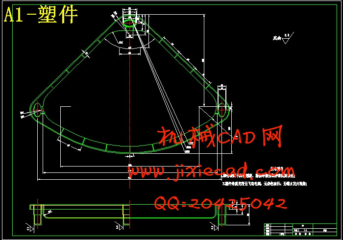
2塑件成型工艺性分析 3
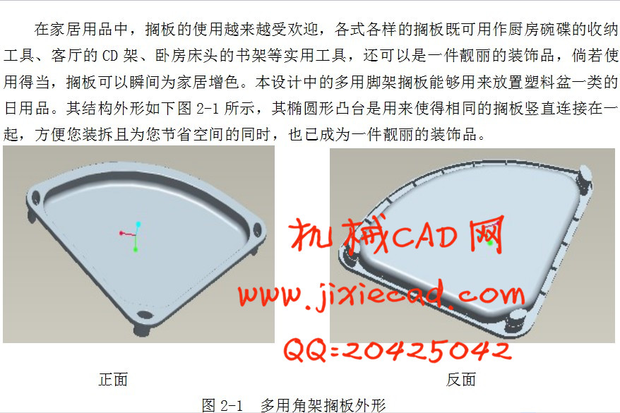
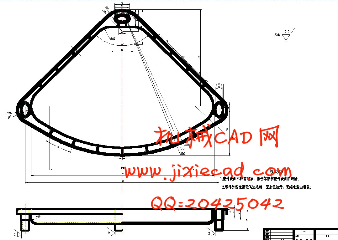
2.1塑件结构分析 3
2.2塑件的工艺性分析 3
2.2.1塑件材料的选择 3
2.2.2 塑件的壁厚 5
2.2.3 塑件的表面质量 5
2.2.4 塑件的精度等级 6
2.2.5 塑件的脱模斜度 6
2.3 PP塑件的注射工艺 7
3 分型面的选择 9
3.1 分型面位置的确定 9
3.2 型腔数目的确定 10
4 注射机型号的选择 11
4.1 体积质量的计算 11
4.2 注射机的选择 11
4.3 注射机相关参数的校核 12
5 注射过程与模流分析 14
5.1 MoldFlow分析软件简介 14
5.2 网格划分 14
5.3 塑件的最佳浇口位置分析 15
5.4 塑件的流动性分析 16
5.4.1 气穴和熔接痕 16
5.4.2 注射位置处压力 17
5.4.3充填时间 17
5.4.4 锁模力 18
5.5塑件的冷却分析 18
5.6 MoldFlow分析总结 19
6 浇注系统的设计 20
6.1 浇注系统的设计原则 20
6.2 主流道的设计和计算 20
6.3 浇口的设计 21
6.4校核主流道的剪切速率 21
7注塑模具成型零件及模具体的设计 22
7.1成型零件的结构设计 22
7.2成型零件钢材的选用 22
7.3成型零件工作尺寸的计算 22
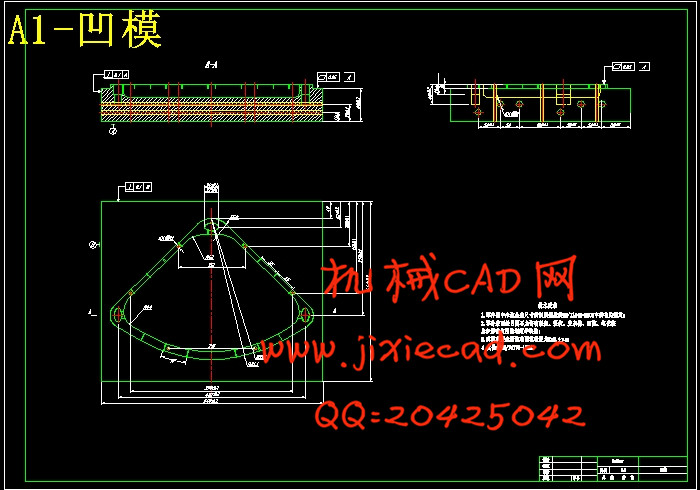
7.3.1凹模径向尺寸的计算 22
7.3.2凹模深度尺寸的计算 23
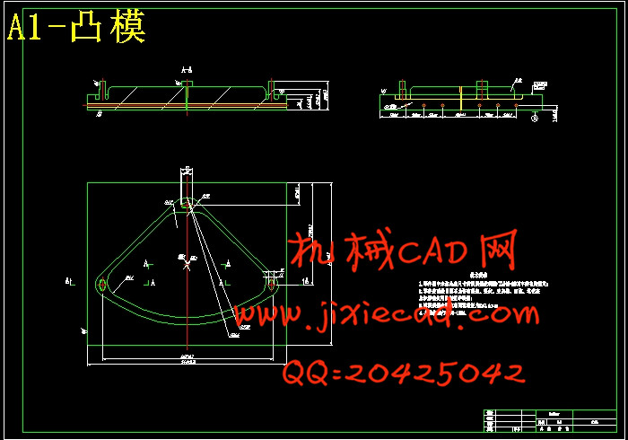
7.3.3凸模径向尺寸的计算 23
7.3.4 凸模高度尺寸的计算 23
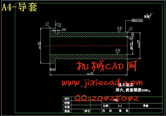
7.4 合模导向机构的设计 23
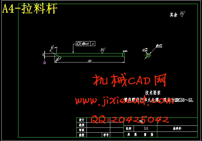
7.5 脱模机构的设计 24
7.5.1脱模力的计算 24
7.5.2塑件脱出机构 25
7.6 模架的确定 26
7.7模架各尺寸的校核 26
8冷却系统及排气系统设计 27
8.1 冷却系统的设计 27
8.1.1 模具温度调节的必要性 27
8.1.2 冷却系统的设计原则 27
8.1.3 冷却水道的设计 27
8.2排气和引气系统的设计 29
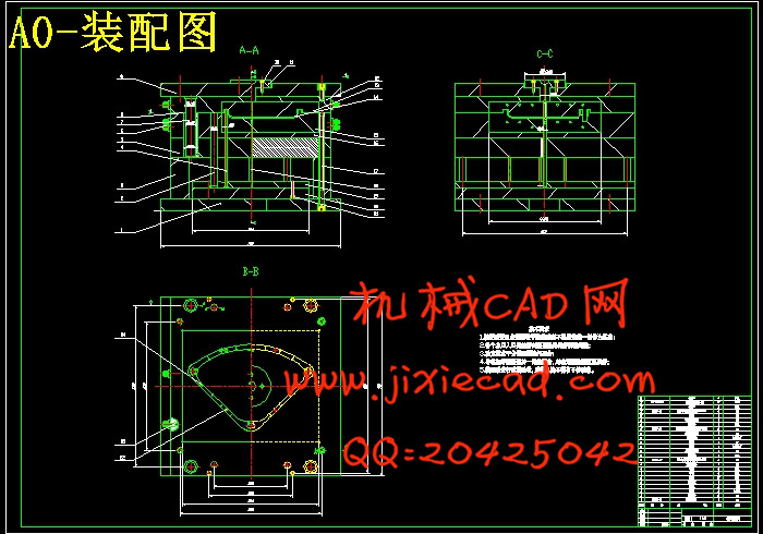
9模具的装配与调试 31
10 基于Mastercam X2的仿真加工 33
10.1 Mastercam X2软件简介 33
10.2 多用角架搁板凸模加工 34
10.2.1 加工坯料及对刀点的确定 34
10.2.2规划曲面挖槽粗加工刀具路径 34
10.2.3 工件参数设置 35
10.2.4 曲面挖槽粗加工实体加工模拟 35
10.2.5规划分型面浅平面精加工刀具路径 36
10.2.6分型面浅平面精加工实体加工模拟 36
10.2.7规划等高外形精加工刀具路径 37
10.2.8 曲面等高外形精加工实体加工模拟 37
10.2.9 规划
10.2.10曲面平行精加工实体加工模拟 39
10.2.11 规划顶面平行铣削精加工刀具路径 39
10.2.12 顶面平行铣削精加工平行铣削实体加工模拟 40
10.3生成加工NC代码 40
结论 42
致谢 43
参考文献 44