设计简介
摘要
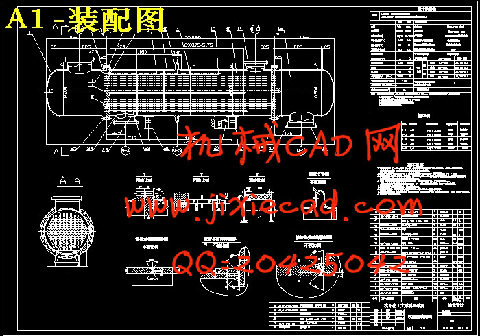
气-液换热器又称回热器,其作用是使节流前的制冷剂液体过冷,使从蒸发器流过来的制冷剂饱和蒸气过热,这样既保证了压缩机工作的安全性,又可以提高整个系统的制冷量。气-液热交换器的结构通常采用壳-盘管式,还有绕管式、套管式等结构。本文主要是根据给定的参数和工艺要求来设计相应的管壳式换热器。本文首先根据工艺条件来进行计算,选定气-液换热器型式,本设计选定固定管板式列管换热器,确定换热器参数。然后进行结构上的设计和强度计算,进行四种工况校核,其结果都满足要求。然后进行接管补强,水压试验,结果也都满足要求。最后再根据标准选取接管、法兰、鞍式支座、垫片等。
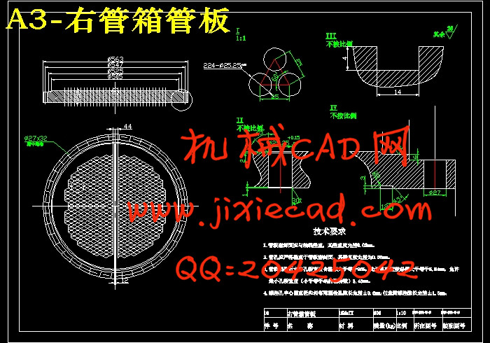
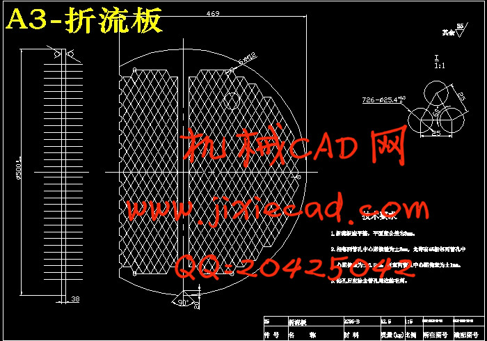
首先要根据已给出的设计温度和设计压力来确定设备的结构形式以及壳程和管程所用的材料,然后根据物料的性质和传热的面积来确定换热管的材料,尺寸和根数。根据换热管的根数来确定换热管的排列方式,并根据换热管的排列和长度来确定筒体的直径以及折流板的选择。进行完了标准件的选取后,再进行各零件间的连接结构的设计,零件材料的选择以及厚度的计算。其中包括了筒体壁厚、封头壁厚、管板壁厚和管箱壁厚的计算,管子的拉脱力和稳定性校核,接管、法兰、容器法兰、支座等的选择及开孔补强设计,管板、折流板以及换热管之间的连接的结构设计,壳体与管板之间的连接处的设计。通过对容器的内径和内外压的计算来确定壳体和封头的厚度并进行强度的校核。然后是对气-液换热器各部件上的零部件的强度设计,有法兰的选择和设计计算与校核,管子拉脱力的计算钩圈及浮头法兰的设计计算与校核。并且还包括了管板的结构设计、滑道结构、防冲挡板的设计以及支座设计。结构设计中的标准件可以按照国家标准根据设计条件直接选取,非标准件,设计完结构后必须对其进行相应的应力校核。
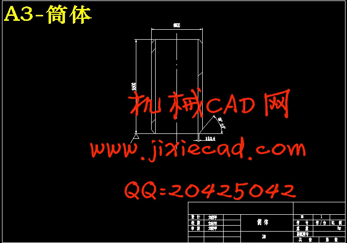
本设计通过对壳体内外的研究,对气-液换热器有了初步的认识,并根据相关知识,进行了一系列相应的设计计算,并最终完成了气氨冷却器总体的结构设计,并绘制出了设备总图及零部件图。其中包括气-液换热器总图,折流板零件图,筒体零件图等。
关键词: 管壳式换热器; 工艺计算; 强度计算
Abstract
This article mainly according to the given parameters and technical requirements to design the corresponding tube heat exchanger. At first, this paper calculated according to the process conditions, select heat exchanger type, the design selected fixed tube plate shell and tube heat exchanger, heat exchanger parameters. Then carries on the structure design and strength calculation, four kinds of working condition checking, the result is meet the requirements. Finally take over reinforcement, hydrostatic test, the result is meet the requirements. According to the standard selection of takeover, flange, saddle support, gaskets.
First according to the given temperature and design pressure to determine the structure of device and the shell side and tube side of the material, then according to the nature of the material and the heat transfer area to determine the heat exchange tube material, size and number. According to the root of the heat exchange tube, the number of heat exchange tube arrangement, and according to the arrangement of heat exchange tube to determine cylinder diameter and length, and the choice of the baffle plate. Connection between the selection of standard parts, parts of the structure of the design, the selection of component materials and the thickness of the calculation. Including the cylinder body wall thickness, head wall thickness and pipe wall thickness and the calculation of wall thickness, tube pulled off force and stability checking, take over, flange, selection of container flange, bearing and opening reinforcement design, tube plate, baffle plate, and the structure design of the connection between the heat exchange tube, between the shell and tube plate joint design. Through the container inner diameter and the internal and external pressure calculation to determine the thickness of the shell and head and strength check. Then every parts of gas-liquid heat exchanger strength design of the parts and components have the choice of the flange and design calculation and checking, hook ring, and the calculation in the design of floating head flange and the checking and calculation of the force of tube pulled off. And also includes the structure design of tube sheet, prevent the impact damper, the design of the track structure and support design. Structure design of standard parts can direct selection according to the design conditions according to the national standard, non-standard, design the structure must be carried out after the corresponding stress checking.
This design through the study of shell inside and outside, have a preliminary understanding of the heat exchanger, and according to the relevant knowledge, made a series of design calculation, and finally complete the overall structure design of diesel oil cooler, drawing equipment assembly drawing and parts drawing. General layout, including the heat exchanger tube bundle, baffle plate parts diagram, tube box parts drawing and so on.
Keywords: heat exchanger; process calculation; strength calculation
目 录
第一章 绪论 1
1.1 课题背景 1
1.2 发展现状及趋势 1
1.3 存在的问题 1
1.4 课题的研究目的和意义 2
第二章 换热器的工艺计算 3
2.1 设计任务和操作条件 3
2.2 确定设计方案 3
2.2.1 两流体温度变化情况 3
2.2.2 流程安排 3
2.3 确定物性数据 3
2.4.3 平均传热温差 4
2.4.4 计算换热面积 4
2.5 核算换热器 4
2.5.1 核算总传热系数 4
2.5.2 核算压强降 6
2.6 工艺结构尺寸 7
2.6.1 管径与管内流速的选择 7
2.6.2 单程传热管数的确定 7
2.6.3 管长度的确定 7
2.6.4 平均传热温度校正及壳程数 7
2.6.5 筒体内径的确定 7
2.6.6 折流板 8
2.6.7 其他附件 8
2.6.8 接管 8
2.7本章小结 9
第三章 管壳式换热器的强度计算 10
3.1 壳体计算 10
3.1.1 筒体计算 10
3.2 前端管箱筒体计算 11
3.3 管箱封头的设计 11
3.4 设计计算 12
3.5 壳程外压作用下的计算 13
3.5.1 按内压设计 13
3.5.2 按外压设计 13
3.6 管板的设计计算 14
3.6.1 设计压力及设计温度的选取 14
3.6.2 结构系数的确定 14
3.6.3 管板厚度 15
3.6.4 换热管轴向应力校核 15
3.6.5 热管与管板连接的拉脱力校核 16
3.7 接管及开孔补强计算 16
3.7.1 外壳接管开孔补强计算 16
3.7.2 管箱接管开孔补强计算 17
3.8 钩圈 18
3.9 分程隔板 18
3.10 其他结构的选择 18
3.10.1 支座选择 18
3.10.2 法兰选择 18
3.10.4 防冲与导流 20
第四章 制造、检验、安装与维修 21
4.1 概述 21
4.2 材料验收 21
4.3 筒体的制造 21
4.4封头的制造 22
4.5 管板的制造 23
4.6 管束的制造 24
4.7 接管的制造 24
4.8装配 25
4.8.1 筒体、法兰的组装与焊接 25
4.8.2 管箱的组装、焊接与加工 25
4.8.3 管束的组装 25
4.8.4 管束、壳体及内件装配 25
4.9 油漆、包装 26
4.10 换热器在使用中常见故障及处理 26
4.10.1 原因 26
4.10.2 现象 26
4.10.3 处理 27
结论 28
参考文献 29
致谢 30
气-液换热器又称回热器,其作用是使节流前的制冷剂液体过冷,使从蒸发器流过来的制冷剂饱和蒸气过热,这样既保证了压缩机工作的安全性,又可以提高整个系统的制冷量。气-液热交换器的结构通常采用壳-盘管式,还有绕管式、套管式等结构。本文主要是根据给定的参数和工艺要求来设计相应的管壳式换热器。本文首先根据工艺条件来进行计算,选定气-液换热器型式,本设计选定固定管板式列管换热器,确定换热器参数。然后进行结构上的设计和强度计算,进行四种工况校核,其结果都满足要求。然后进行接管补强,水压试验,结果也都满足要求。最后再根据标准选取接管、法兰、鞍式支座、垫片等。
首先要根据已给出的设计温度和设计压力来确定设备的结构形式以及壳程和管程所用的材料,然后根据物料的性质和传热的面积来确定换热管的材料,尺寸和根数。根据换热管的根数来确定换热管的排列方式,并根据换热管的排列和长度来确定筒体的直径以及折流板的选择。进行完了标准件的选取后,再进行各零件间的连接结构的设计,零件材料的选择以及厚度的计算。其中包括了筒体壁厚、封头壁厚、管板壁厚和管箱壁厚的计算,管子的拉脱力和稳定性校核,接管、法兰、容器法兰、支座等的选择及开孔补强设计,管板、折流板以及换热管之间的连接的结构设计,壳体与管板之间的连接处的设计。通过对容器的内径和内外压的计算来确定壳体和封头的厚度并进行强度的校核。然后是对气-液换热器各部件上的零部件的强度设计,有法兰的选择和设计计算与校核,管子拉脱力的计算钩圈及浮头法兰的设计计算与校核。并且还包括了管板的结构设计、滑道结构、防冲挡板的设计以及支座设计。结构设计中的标准件可以按照国家标准根据设计条件直接选取,非标准件,设计完结构后必须对其进行相应的应力校核。
本设计通过对壳体内外的研究,对气-液换热器有了初步的认识,并根据相关知识,进行了一系列相应的设计计算,并最终完成了气氨冷却器总体的结构设计,并绘制出了设备总图及零部件图。其中包括气-液换热器总图,折流板零件图,筒体零件图等。
关键词: 管壳式换热器; 工艺计算; 强度计算
Abstract
This article mainly according to the given parameters and technical requirements to design the corresponding tube heat exchanger. At first, this paper calculated according to the process conditions, select heat exchanger type, the design selected fixed tube plate shell and tube heat exchanger, heat exchanger parameters. Then carries on the structure design and strength calculation, four kinds of working condition checking, the result is meet the requirements. Finally take over reinforcement, hydrostatic test, the result is meet the requirements. According to the standard selection of takeover, flange, saddle support, gaskets.
First according to the given temperature and design pressure to determine the structure of device and the shell side and tube side of the material, then according to the nature of the material and the heat transfer area to determine the heat exchange tube material, size and number. According to the root of the heat exchange tube, the number of heat exchange tube arrangement, and according to the arrangement of heat exchange tube to determine cylinder diameter and length, and the choice of the baffle plate. Connection between the selection of standard parts, parts of the structure of the design, the selection of component materials and the thickness of the calculation. Including the cylinder body wall thickness, head wall thickness and pipe wall thickness and the calculation of wall thickness, tube pulled off force and stability checking, take over, flange, selection of container flange, bearing and opening reinforcement design, tube plate, baffle plate, and the structure design of the connection between the heat exchange tube, between the shell and tube plate joint design. Through the container inner diameter and the internal and external pressure calculation to determine the thickness of the shell and head and strength check. Then every parts of gas-liquid heat exchanger strength design of the parts and components have the choice of the flange and design calculation and checking, hook ring, and the calculation in the design of floating head flange and the checking and calculation of the force of tube pulled off. And also includes the structure design of tube sheet, prevent the impact damper, the design of the track structure and support design. Structure design of standard parts can direct selection according to the design conditions according to the national standard, non-standard, design the structure must be carried out after the corresponding stress checking.
This design through the study of shell inside and outside, have a preliminary understanding of the heat exchanger, and according to the relevant knowledge, made a series of design calculation, and finally complete the overall structure design of diesel oil cooler, drawing equipment assembly drawing and parts drawing. General layout, including the heat exchanger tube bundle, baffle plate parts diagram, tube box parts drawing and so on.
Keywords: heat exchanger; process calculation; strength calculation
目 录
第一章 绪论 1
1.1 课题背景 1
1.2 发展现状及趋势 1
1.3 存在的问题 1
1.4 课题的研究目的和意义 2
第二章 换热器的工艺计算 3
2.1 设计任务和操作条件 3
2.2 确定设计方案 3
2.2.1 两流体温度变化情况 3
2.2.2 流程安排 3
2.3 确定物性数据 3
2.4.3 平均传热温差 4
2.4.4 计算换热面积 4
2.5 核算换热器 4
2.5.1 核算总传热系数 4
2.5.2 核算压强降 6
2.6 工艺结构尺寸 7
2.6.1 管径与管内流速的选择 7
2.6.2 单程传热管数的确定 7
2.6.3 管长度的确定 7
2.6.4 平均传热温度校正及壳程数 7
2.6.5 筒体内径的确定 7
2.6.6 折流板 8
2.6.7 其他附件 8
2.6.8 接管 8
2.7本章小结 9
第三章 管壳式换热器的强度计算 10
3.1 壳体计算 10
3.1.1 筒体计算 10
3.2 前端管箱筒体计算 11
3.3 管箱封头的设计 11
3.4 设计计算 12
3.5 壳程外压作用下的计算 13
3.5.1 按内压设计 13
3.5.2 按外压设计 13
3.6 管板的设计计算 14
3.6.1 设计压力及设计温度的选取 14
3.6.2 结构系数的确定 14
3.6.3 管板厚度 15
3.6.4 换热管轴向应力校核 15
3.6.5 热管与管板连接的拉脱力校核 16
3.7 接管及开孔补强计算 16
3.7.1 外壳接管开孔补强计算 16
3.7.2 管箱接管开孔补强计算 17
3.8 钩圈 18
3.9 分程隔板 18
3.10 其他结构的选择 18
3.10.1 支座选择 18
3.10.2 法兰选择 18
3.10.4 防冲与导流 20
第四章 制造、检验、安装与维修 21
4.1 概述 21
4.2 材料验收 21
4.3 筒体的制造 21
4.4封头的制造 22
4.5 管板的制造 23
4.6 管束的制造 24
4.7 接管的制造 24
4.8装配 25
4.8.1 筒体、法兰的组装与焊接 25
4.8.2 管箱的组装、焊接与加工 25
4.8.3 管束的组装 25
4.8.4 管束、壳体及内件装配 25
4.9 油漆、包装 26
4.10 换热器在使用中常见故障及处理 26
4.10.1 原因 26
4.10.2 现象 26
4.10.3 处理 27
结论 28
参考文献 29
致谢 30