设计简介
摘要
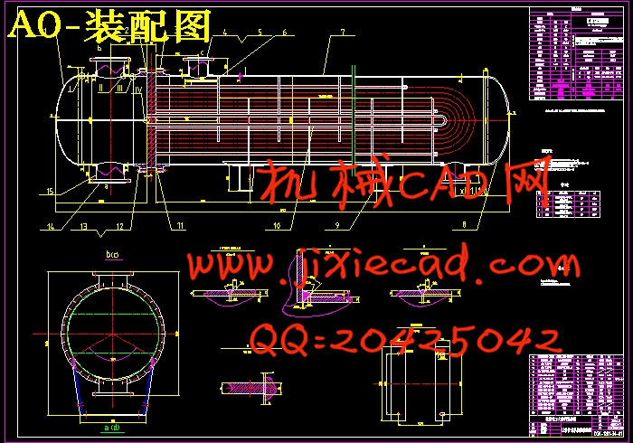
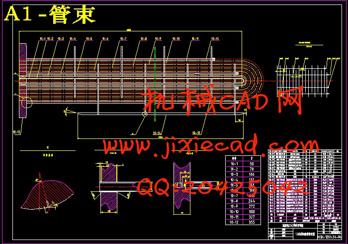
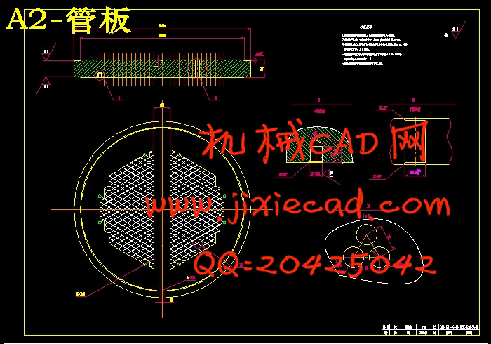
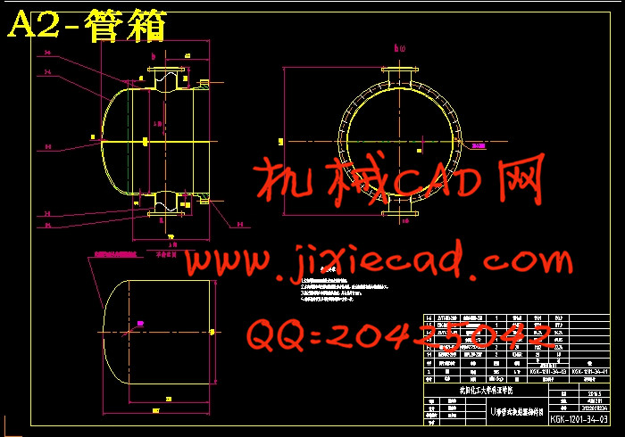
本文介绍了U型管换热器整体的结构与强度设计计算。U型管换热器是将管子弯成U型,管子的两端均固定在同一个管板上。出于壳体和管子的分开,管束可以进行自由的伸缩,因此没有热应力,热的补偿功能好;管程采用的是双管程,流程比较较长,流速比较高,传热性能较好,承压的能力较强。管束可从壳体抽出,优点是方便检修和清洁,而且结构简单造价便宜。缺点是管内清洗困难,这就要求管内通过的流体必须是清洁不易产生污垢的物料[1]。
它的主要特点是在单位体积内传热的面积较大而且传热效果比较好。除此之外,它的结构简单,操作的弹性也大,所以在高温、高压的情况下以及在大型装备的应用上更多的使用管壳式换热器。而U型管式换热器一般用在高温高压状态下,尤其是高压下,这就要求在弯管段要加强壁厚来弥补弯管后管壁的减薄[1]。
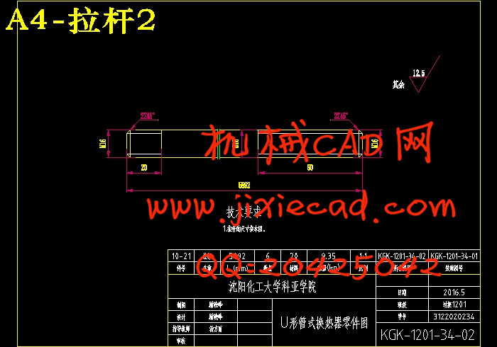
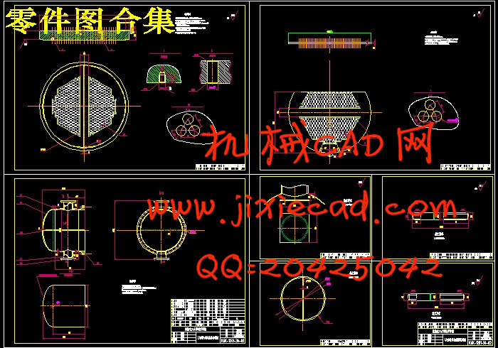
这次设计的题目是“流量为100t/h U形管式换热器”,U型管式换热器是管壳式换热器里的一种,它的结构主要包括管板、壳体、管束管箱、封头、换热管、支座等零其他部件,重量相对比较轻。在这次的设计中由于设计的压力和温度都比较高,因此设计的要求比较高,在对换热器的设计中,主要对其结构、强度进行了设计以及对零部件的选型和工艺设计。换热器的材料选用恰当,主要结构的尺寸也进行了合理的选择,这些均能够满足换热器在强度、刚度、稳定性以及水压试验等校核方面的要求。本次U型管式换热器设计的壳程介质为油,管程介质为水。流量为100t/h,壳程的工作温度为190℃,管程的工作温度为70℃,壳程的设计温度为200℃,管程的设计温度为90℃。在其结构上安装有八块折流板,以增加流体的湍流速度。设计压力为管程2.0MPa,壳程1.5MPa。依据给定的条件,查看GB150-2011《钢制压力容器》,GB151-1999《管壳式换热器》以及换热器手册等标准,通过试算法获得总传热系数,所得传热面积为193.3m².考虑到介质特性,采用φ25×2.5×6000的20#的无缝钢管,本设计采用420根换热管可以满足换热量。接管法兰我选择了板式平焊法兰,并采用鞍式支座支撑。在本次毕业设计过程中我已经完成了文献综述,设计说明书,一张总装配图和四张零件图的绘制。
换热器在工业、农业等许多的领域运用十分的广泛,当然在日常的生活中和现实中传热设备也随处可以见到,这是不可能缺少的工艺设备和单元之一。随着研究的不断深入,工业应用也取得了显著的成效。并且在许多化工单元操作的场合也作为一种十分重要的附属设备进行使用,所以在化工生产中换热器也占有着非常非常重要的地位。
关键词: U型管换热器; 结构; 强度;设计计算
Abstract
This paper describes the U-tube heat exchanger overall structure and strength of the design calculations. U-tube heat exchanger tube is bent into a U-shape, both ends of the tubes are fixed in the same tube plate. Since the housing and separate tubes, tube bundle can freely stretch without heat stress, good compensation performance heat; tube uses a dual tube, process is relatively long, high velocity, good heat transfer performance, pressure the ability. Can be withdrawn from the housing tube bundle, the advantage of easy maintenance and cleaning, and low cost structure is simple. The disadvantage is difficult to clean the inner tube, which requires fluid through the inner tube material must be easy to produce clean dirt[2].
Its main feature is the heat transfer area per unit volume and greater heat transfer effect is better. In addition, its simple structure, flexible operation is also large, so in the case of high temperature, high pressure, and more use of shell and tube heat exchangers in the application of large-scale equipment. The U-tube heat exchanger is generally used at high temperature and pressure conditions, especially under high pressure, which requires strengthening the wall thickness of the elbow segment to make up after the bend wall thinning.
The design is entitled "Flow of 100t / h U-tube type heat exchangers", U-tube heat exchanger is a shell and tube heat exchanger in which one of its main structure comprises a tube plate, shell zero other parts bundle header, head, heat transfer tubes, bearings, etc., are relatively light weight. In this design because of the design pressure and temperature are high, so the design requirements, the design of the heat exchanger structure, strength and design of components selection and process design. The selection of appropriate heat exchanger material, the main dimensions of the structure were also a reasonable choice, are able to meet the heat exchanger in terms of checking the strength, stiffness, stability and hydrostatic test and other requirements. The U-tube heat exchanger design shell medium is oil, tube medium is water. Flow rate of 100t / h, the shell of the operating temperature of 190 ℃, tube operating temperature of 70 ℃, shell design temperature of 200 ℃, the tube design temperature is 90 ℃. In its structure mounted eight baffles to increase the velocity of the fluid turbulence. Tube design pressure of 2.0MPa, shell 1.5MPa. Based on the given conditions, consult GB150-2011 "steel pressure vessel", GB151-1999 "shell and tube heat exchanger," as well as heat exchangers manuals and other standards, to get the total heat transfer coefficient through the test algorithm, and the resulting heat transfer area 193.3m². Taking into account the characteristics of the medium, the use of φ25 × 20 # seamless steel pipe of 2.5 × 6000, the design uses 420 calories of heat transfer tubes to meet the change. I chose to take over the flange plate welded flange, and the choice of saddle supports support. In this graduation design process I've done a literature review, design specifications, draw a general assembly drawings and four part drawing.
Heat in many areas of use in industry, agriculture and other very widely, of course, in everyday life and the reality of heat transfer equipment also can be seen everywhere, it is the lack of equipment and one unit can not process. With the deepening of research, industrial applications has also made remarkable achievements. And in many chemical unit operation occasions as a very important ancillary equipment may be used, so the heat exchanger in chemical production also occupies a very important position[3].
Keywords: U-tube heat exchanger; structure; strength; design calculati
目 录
本文介绍了U型管换热器整体的结构与强度设计计算。U型管换热器是将管子弯成U型,管子的两端均固定在同一个管板上。出于壳体和管子的分开,管束可以进行自由的伸缩,因此没有热应力,热的补偿功能好;管程采用的是双管程,流程比较较长,流速比较高,传热性能较好,承压的能力较强。管束可从壳体抽出,优点是方便检修和清洁,而且结构简单造价便宜。缺点是管内清洗困难,这就要求管内通过的流体必须是清洁不易产生污垢的物料[1]。
它的主要特点是在单位体积内传热的面积较大而且传热效果比较好。除此之外,它的结构简单,操作的弹性也大,所以在高温、高压的情况下以及在大型装备的应用上更多的使用管壳式换热器。而U型管式换热器一般用在高温高压状态下,尤其是高压下,这就要求在弯管段要加强壁厚来弥补弯管后管壁的减薄[1]。
这次设计的题目是“流量为100t/h U形管式换热器”,U型管式换热器是管壳式换热器里的一种,它的结构主要包括管板、壳体、管束管箱、封头、换热管、支座等零其他部件,重量相对比较轻。在这次的设计中由于设计的压力和温度都比较高,因此设计的要求比较高,在对换热器的设计中,主要对其结构、强度进行了设计以及对零部件的选型和工艺设计。换热器的材料选用恰当,主要结构的尺寸也进行了合理的选择,这些均能够满足换热器在强度、刚度、稳定性以及水压试验等校核方面的要求。本次U型管式换热器设计的壳程介质为油,管程介质为水。流量为100t/h,壳程的工作温度为190℃,管程的工作温度为70℃,壳程的设计温度为200℃,管程的设计温度为90℃。在其结构上安装有八块折流板,以增加流体的湍流速度。设计压力为管程2.0MPa,壳程1.5MPa。依据给定的条件,查看GB150-2011《钢制压力容器》,GB151-1999《管壳式换热器》以及换热器手册等标准,通过试算法获得总传热系数,所得传热面积为193.3m².考虑到介质特性,采用φ25×2.5×6000的20#的无缝钢管,本设计采用420根换热管可以满足换热量。接管法兰我选择了板式平焊法兰,并采用鞍式支座支撑。在本次毕业设计过程中我已经完成了文献综述,设计说明书,一张总装配图和四张零件图的绘制。
换热器在工业、农业等许多的领域运用十分的广泛,当然在日常的生活中和现实中传热设备也随处可以见到,这是不可能缺少的工艺设备和单元之一。随着研究的不断深入,工业应用也取得了显著的成效。并且在许多化工单元操作的场合也作为一种十分重要的附属设备进行使用,所以在化工生产中换热器也占有着非常非常重要的地位。
关键词: U型管换热器; 结构; 强度;设计计算
Abstract
This paper describes the U-tube heat exchanger overall structure and strength of the design calculations. U-tube heat exchanger tube is bent into a U-shape, both ends of the tubes are fixed in the same tube plate. Since the housing and separate tubes, tube bundle can freely stretch without heat stress, good compensation performance heat; tube uses a dual tube, process is relatively long, high velocity, good heat transfer performance, pressure the ability. Can be withdrawn from the housing tube bundle, the advantage of easy maintenance and cleaning, and low cost structure is simple. The disadvantage is difficult to clean the inner tube, which requires fluid through the inner tube material must be easy to produce clean dirt[2].
Its main feature is the heat transfer area per unit volume and greater heat transfer effect is better. In addition, its simple structure, flexible operation is also large, so in the case of high temperature, high pressure, and more use of shell and tube heat exchangers in the application of large-scale equipment. The U-tube heat exchanger is generally used at high temperature and pressure conditions, especially under high pressure, which requires strengthening the wall thickness of the elbow segment to make up after the bend wall thinning.
The design is entitled "Flow of 100t / h U-tube type heat exchangers", U-tube heat exchanger is a shell and tube heat exchanger in which one of its main structure comprises a tube plate, shell zero other parts bundle header, head, heat transfer tubes, bearings, etc., are relatively light weight. In this design because of the design pressure and temperature are high, so the design requirements, the design of the heat exchanger structure, strength and design of components selection and process design. The selection of appropriate heat exchanger material, the main dimensions of the structure were also a reasonable choice, are able to meet the heat exchanger in terms of checking the strength, stiffness, stability and hydrostatic test and other requirements. The U-tube heat exchanger design shell medium is oil, tube medium is water. Flow rate of 100t / h, the shell of the operating temperature of 190 ℃, tube operating temperature of 70 ℃, shell design temperature of 200 ℃, the tube design temperature is 90 ℃. In its structure mounted eight baffles to increase the velocity of the fluid turbulence. Tube design pressure of 2.0MPa, shell 1.5MPa. Based on the given conditions, consult GB150-2011 "steel pressure vessel", GB151-1999 "shell and tube heat exchanger," as well as heat exchangers manuals and other standards, to get the total heat transfer coefficient through the test algorithm, and the resulting heat transfer area 193.3m². Taking into account the characteristics of the medium, the use of φ25 × 20 # seamless steel pipe of 2.5 × 6000, the design uses 420 calories of heat transfer tubes to meet the change. I chose to take over the flange plate welded flange, and the choice of saddle supports support. In this graduation design process I've done a literature review, design specifications, draw a general assembly drawings and four part drawing.
Heat in many areas of use in industry, agriculture and other very widely, of course, in everyday life and the reality of heat transfer equipment also can be seen everywhere, it is the lack of equipment and one unit can not process. With the deepening of research, industrial applications has also made remarkable achievements. And in many chemical unit operation occasions as a very important ancillary equipment may be used, so the heat exchanger in chemical production also occupies a very important position[3].
Keywords: U-tube heat exchanger; structure; strength; design calculati
目 录
第一章换热器的结构类型与发展 1
1.1 换热器的概述 1
1.2 换热器的分类 1
1.2.1 换热器按传热方式分类 1
1.2.2 换热器按用途分类 2
1.2.3 换热器按其结构分类 2
1.3 换热器的结构介绍 3
1.4 换热器的主要组合部件 4
1.5 换热器的设计 5
1.5.1 估算传热面积初选换热器型号 5
1.5.2 计算管程和壳程压强降 5
1.5.3 核算总传热系数和传热面积 5
1.6 换热器的发展 5
第二章U型管换热器传热工艺计算 7
2.1 原始数据 7
2.2 确定定性温度及物性数据 7
2.2.1 管程冷水的定性温度 7
2.2.2壳程煤油的定性温度 7
2.3 煤油的传热量与冷水流量的计算 8
2.4 管程换热系数的计算 9
2.5 结构的初步设计 9
2.6 壳程换热系数计算 10
2.7 传热系数计算 11
2.8 管壁温度计算 11
2.9 管程压力降计算 11
2.10 壳程压力降计算 13
第三章换热器强度计算与应力校核 14
3.1 换热管材料及规格选择和根数的确定 14
3.2 管子的排列方式 14
3.3 筒体内径的确定 14
3.4 筒体厚壁的确定 15
3.5 筒体的液压试验 16
3.6 壳程标准椭圆形封头厚度的计算 16
3.7 管程标准椭圆形封头厚度的计算 17
3.8 容器法兰的选择 18
3.8.1 设备法兰的选择 18
3.8.2 接管法兰的选择 18
3.9 管板的设计 21
3.10 管相短节壁厚的计算 22
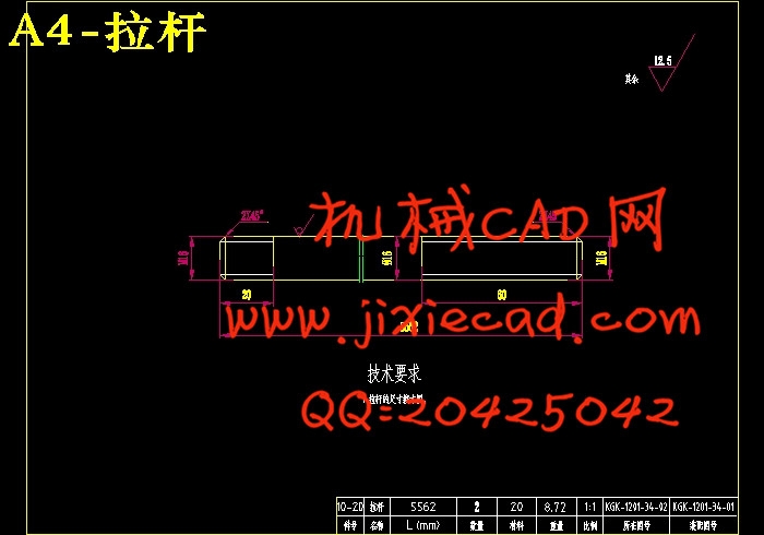
3.11 拉杆和定距管的确定 23
3.11.1 拉杆的结构型式 23
3.11.2 拉杆的尺寸 24
3.11.3 定距管尺寸 24
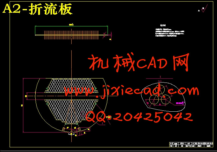
3.12 折流板的选择 25
3.12.1 选型 25
3.12.2 折流板尺寸 25
3.12.3 换热管无支撑跨距或折流板间距 25
3.12.4 折流板厚度 25
3.12.5 折流板直径 25
3.12.6 折流板管孔直径 25
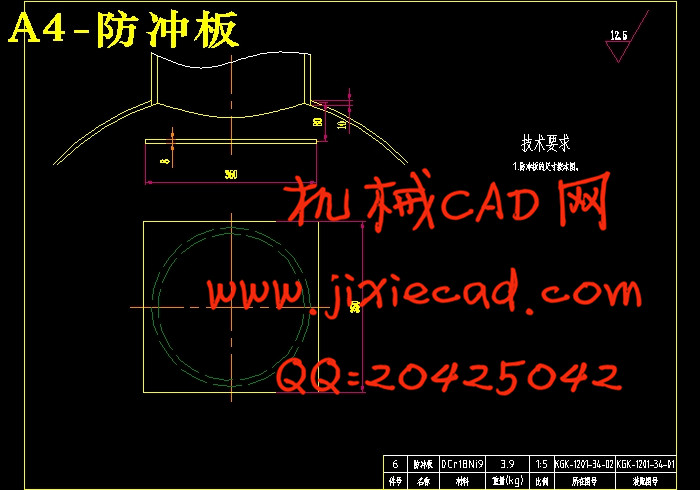
3.13 防冲板尺寸的确定 26
3.14 开孔补强计算 26
3.15 分程隔板厚度选取 29
3.16 支座的选择及应力校核 29
3.16.1 支座的选择 29
3.16.2 鞍座的应力校核 30
参考文献 34
致谢 35