设计简介
摘要
换热器可按照其结构形式分类:有固定管板式换热器;填料函式换热器;浮头式换热器;U形管换热器。固定管板式换热器类属于管壳式换热器,是管壳式换热器的一种标准结构,也是目前应用比较广泛的一种换热器[1]。这类换热器拥有许多特点:结构简易,紧凑,适用面很广泛,安全系数很高,选料面可以很广,成本很低廉,换热表面的清洗也极为方便。因为固定管板式换热器可以承受比较高的温度和比较高的操作压力,所以在大型换热器和高温高压换热器中,占首要地位。固定管板式换热器有许多特点,最突出的特点是锻件少、比较便宜、密封性能好。由于它的壳程无法机械清洗,所以管子腐蚀后会和壳体一起报废,设备的寿命就会降低[2]。所以当所需流量不同时,需要根据不同的流量设计不同的换热器。
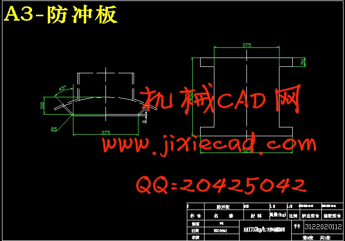
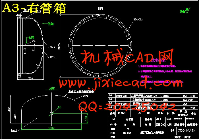
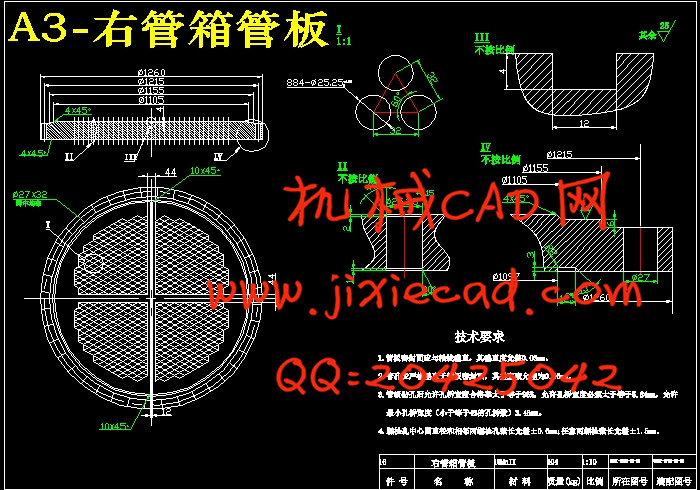
首先根据给出的设计温度和设计压力来确定设备的结构形式以及壳程和管程的材料,然后根据物料的性质和传热的面积来确定换热管的材料,尺寸和根数。根据换热管的根数确定换热管的排列,并根据换热管的排列和长度来确定筒体直径以及折流板的选择。通过对容器的内径和内外压的计算来确定壳体和封头的厚度并进行强度的校核。然后是对换热器各部件的零部件的强度设计,有法兰的选择和设计计算与校核,钩圈及浮头法兰的设计计算与校核和管子拉脱力的计算。并且还包括管板的结构设计、防冲挡板、滑道结构的设计以及支座设计。结构设计中的标准件可以按照国家标准根据设计条件直接选取,非标准件,设计完结构后必须进行相应的应力校核。通过查阅GB150-2011《钢制压力容器》和GB151-1999《管壳式换热器》以及GB和JB等标准以及查看设计要求,我对固定管板式换热器进行了结构设计和CAD绘图。进行了标准件的选取,零件间连接结构的设计,零件材料的选择以及厚度的计算。其中包括了筒体壁厚、封头壁厚、管板壁厚和管箱壁厚的计算,管子拉脱力和稳定性校核,接管、法兰、容器法兰、支座等的选择及开孔补强设计,管板、折流板以及换热管之间的连接的结构设计,壳体与管板之间的连接处的设计。
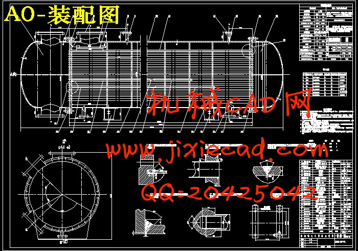
随着经济的发展,现有的科技成果为我们的生活带来了很大的方便,换热器的设计技术也在不断地更新,以后的应用前景将会更加美好。根据设计要求,绘制了一张总装配图和两张零部件图。
关键词: 换热器; 结构; 计算; 校核
Abstract
Heat exchanger according to its structure form can be divided into: fixed tube plate heat exchanger; Stuffing box heat exchanger; Floating head heat exchanger; U-tube heat exchanger[3]. Fixed tube plate heat exchanger tube and shell heat exchanger, tube heat exchanger is a kind of typical structure, also is a kind of heat exchanger is applied more widely. This kind of heat exchanger with many features: simple structure, compact, widely applicable, high safety coefficient, the material widely, low cost, so the heat exchange surface cleaning is extremely convenient. Due to the fixed tube plate heat exchanger can withstand high temperature and high pressure operation, so in the large-scale heat exchanger with high temperature and high pressure heat exchanger, dominate. Fixed tube plate heat exchanger has many features, the most outstanding characteristic is less forgings, cheaper, sealed performance is good. Due to the shell side cannot mechanical cleaning, so after the pipe corrosion will be scrapped, along with shell will reduce equipment life[4]. So when the flow is not required at the same time, need according to the different heat exchanger of different flow design.
First according to the given temperature and design pressure to determine the structure of device and the shell side and tube side of the material, then according to the material properties and the heat transfer area to determine the heat exchange tube material, size, number of root. According to the root of the heat exchange tube, the number of heat exchange tube arrangement, and according to the arrangement of heat exchange tube to determine cylinder diameter and length, and the choice of the baffle plate. Through the container inner diameter and the internal and external pressure calculation to determine the thickness of the shell and head and intensity. And then to various components of the heat exchanger strength design of the parts and components have the choice of the flange and design calculation and checking, hook ring, and the calculation in the design of floating head flange and the checking and calculation of the force of tube pulled off. Includes the structure design of tube sheet, prevent the impact damper, the design of the track structure and support design[5]. The structure design of standard parts can be reference to national standards according to the design conditions of direct selection; After non standard parts, design the structure must be corresponding stress checking. By looking at GB150-2011 "steel pressure vessel" and the tube and shell heat exchanger and GB151-1999 GB and JB standard and view the design requirements, I fixed tube plate heat exchanger for the structure design and CAD drawing. Connection between the selection of standard parts, parts of the structure of the design, the selection of component materials and the thickness of the calculation. Including the cylinder body wall thickness, head wall thickness and pipe wall thickness and the calculation of wall thickness, tube pulled off force and stability checking, take over, flange, selection of container flange, bearing and opening reinforcement design, tube plate, baffle plate and the connection between the structure design of heat exchange tube, the design of the junctions between the shell and tube plate.
With the development of economy, the existing scientific and technological achievements brought great convenience for our life, the design of heat exchanger technology is also in constant updates, future application prospect will be more beautiful. According to the design requirements, to draw a general assembly drawing and the two parts drawing.
Key words: Heat exchanger; Structure; Calculation; check
目 录
第一章 绪论 3
1.1 换热器概述 3
1.2 换热器类型 3
1.2.1 卧式壳程换热器 3
1.2.2 卧式管程换热器 3
1.2.3 立式壳程换热器 3
1.2.4 管内向下流动的立式管程换热器 3
1.2.5 向上流动的立式管程换热器 3
1.3 换热器发展前景 3
1.4 固定管板式换热器总体设计 3
1.5 本文研究内容 3
第二章 工艺计算 3
2.1 设计条件 3
2.2 确定物性数 3
2.3 换热器的类型与流动空间的确定 3
2.4 估算传热面积 3
2.4.1 二甲胺蒸气用量 3
2.4.2 热负荷计算 3
2.4.3 计算有效平均温度差 3
2.4.4 估算传热面积 3
2.4.5 选工艺尺寸计算 3
2.4.6 管程数和传热管数 3
2.4.7 平均传热温差的校正以及壳程数的选取 3
2.4.8 管子排列 3
2.4.9 管心距 3
2.4.10 壳体内径 3
2.4.11 折流板 3
2.4.12 换热器核算及壳程表面传热系数 3
2.4.13 管内表面传热系数 3
2.4.14 污垢热阻和管壁热阻 3
2.4.15 传热系数 3
2.4.16 传热面积裕度 3
2.4.17 传热管和壳体壁温核算 3
2.4.18 压降校核 3
2.4.19 壳程流体阻力 3
2.5 换热器主要结构尺寸和计算结果 3
第三章 结构设计 3
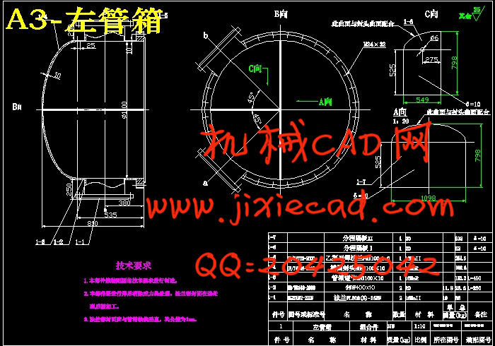
3.1 壳体、管箱壳体和封头的设计 3
3.1.1 壁厚的确定 3
3.1.2 管箱法兰和垫片确定 3
3.1.3 箱壳体壁厚的确定 3
3.1.4 标准椭圆封头的厚度确定 3
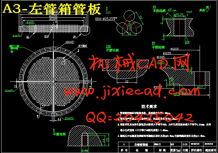
3.2 管板与换热管设计 3
3.3 进出口的设计 3
3.3.1 接管的设计 3
3.3.2 接管外伸长度 3
3.3.3 排气、排液管 3
3.3.4 壳程接管位置的最小距离 3
3.3.5 管箱接管尺寸的最小位置 3
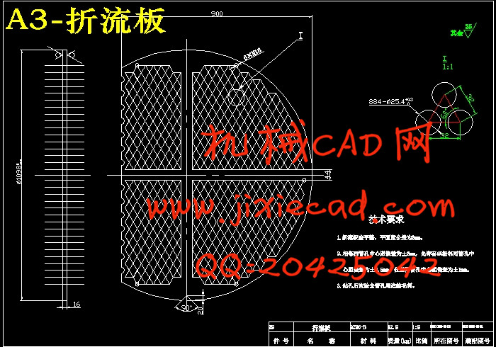
3.4 折流板或支持板尺寸 3
3.4.1 折流板缺口高度和最小厚度 3
3.4.2 折流板和折流板孔径 3
3.4.3 折流板直径及允许偏差 3
3.4.4 折流板的布置及质量计算 3
3.5 防冲挡板 3
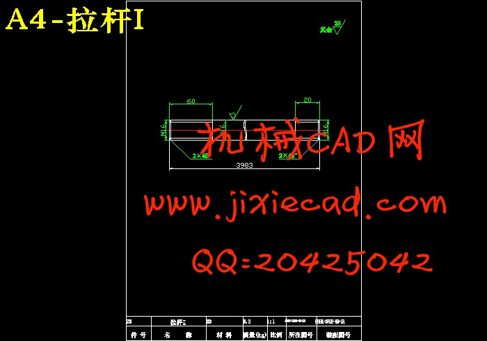
3.6 拉杆与定距管 3
3.6.1 拉杆的尺寸 3
3.6.2 拉杆的直径和数量 3
3.6.3 拉杆的位置、定距管尺寸及鞍座选用 3
第四章 强度计算 3
4.1 壳体、管箱壳体和封头校核 3
4.1.1 对壳体进行强度校核 3
4.1.2 压力试验强度校核 3
4.1.3 管箱壳体校核 3
4.1.4 压力试验强度校核 3
4.1.5 对椭圆封头进行强度校核 3
4.1.6 压力试验强度校核 3
4.2 接管开孔补强 3
4.2.1 蒸汽进出口的接管有关参数的选定 3
4.2.2 有效补强范围的确定 3
4.2.3 有效补强面积 3
4.2.4 冷却水进出口的接管有关参数的选定 3
4.2.5 开孔处所需的最小补强面积 3
4.2.6 有效补强范围的确定 3
4.2.7 有效补强面积 3
4.3 膨胀节 3
4.3.1 管子拉脱力计算 3
4.3.2 膨胀节设置计算 3
4.4 管板校核 3
4.4.1 结构尺寸参数 3
4.4.2 壳程圆筒材料和换热管材料 3
4.4.3 管板、法兰、螺栓、垫片材料 3
4.4.4 管子的许用应力 3
4.4.5 垫片压紧力作用中心圆直径和面积 3
4.4.6 管板布管区当量直径和系数计算 3
4.4.7 基本法兰力矩 3
4.4.8 管程压力操作工况下法兰力矩 3
4.4.9 换热管与壳体圆筒的热膨胀应变形差 3
4.4.10 管箱圆筒与法兰的旋转刚度参数 3
4.4.11 管子厚度和加强系数 3
4.4.12 管板周边无量纲宽度和壳体法兰参数 3
4.4.13 旋转刚度无量纲参数、确定系数 3
4.4.14 设计条件不同危险组合土况的应力计算 3
4.4.15 四种危险工况的各种应力计算与校核 3
4.5 设计值总汇 3
第五章 结论 3
参考文献 3
致谢 3
换热器可按照其结构形式分类:有固定管板式换热器;填料函式换热器;浮头式换热器;U形管换热器。固定管板式换热器类属于管壳式换热器,是管壳式换热器的一种标准结构,也是目前应用比较广泛的一种换热器[1]。这类换热器拥有许多特点:结构简易,紧凑,适用面很广泛,安全系数很高,选料面可以很广,成本很低廉,换热表面的清洗也极为方便。因为固定管板式换热器可以承受比较高的温度和比较高的操作压力,所以在大型换热器和高温高压换热器中,占首要地位。固定管板式换热器有许多特点,最突出的特点是锻件少、比较便宜、密封性能好。由于它的壳程无法机械清洗,所以管子腐蚀后会和壳体一起报废,设备的寿命就会降低[2]。所以当所需流量不同时,需要根据不同的流量设计不同的换热器。
首先根据给出的设计温度和设计压力来确定设备的结构形式以及壳程和管程的材料,然后根据物料的性质和传热的面积来确定换热管的材料,尺寸和根数。根据换热管的根数确定换热管的排列,并根据换热管的排列和长度来确定筒体直径以及折流板的选择。通过对容器的内径和内外压的计算来确定壳体和封头的厚度并进行强度的校核。然后是对换热器各部件的零部件的强度设计,有法兰的选择和设计计算与校核,钩圈及浮头法兰的设计计算与校核和管子拉脱力的计算。并且还包括管板的结构设计、防冲挡板、滑道结构的设计以及支座设计。结构设计中的标准件可以按照国家标准根据设计条件直接选取,非标准件,设计完结构后必须进行相应的应力校核。通过查阅GB150-2011《钢制压力容器》和GB151-1999《管壳式换热器》以及GB和JB等标准以及查看设计要求,我对固定管板式换热器进行了结构设计和CAD绘图。进行了标准件的选取,零件间连接结构的设计,零件材料的选择以及厚度的计算。其中包括了筒体壁厚、封头壁厚、管板壁厚和管箱壁厚的计算,管子拉脱力和稳定性校核,接管、法兰、容器法兰、支座等的选择及开孔补强设计,管板、折流板以及换热管之间的连接的结构设计,壳体与管板之间的连接处的设计。
随着经济的发展,现有的科技成果为我们的生活带来了很大的方便,换热器的设计技术也在不断地更新,以后的应用前景将会更加美好。根据设计要求,绘制了一张总装配图和两张零部件图。
关键词: 换热器; 结构; 计算; 校核
Abstract
Heat exchanger according to its structure form can be divided into: fixed tube plate heat exchanger; Stuffing box heat exchanger; Floating head heat exchanger; U-tube heat exchanger[3]. Fixed tube plate heat exchanger tube and shell heat exchanger, tube heat exchanger is a kind of typical structure, also is a kind of heat exchanger is applied more widely. This kind of heat exchanger with many features: simple structure, compact, widely applicable, high safety coefficient, the material widely, low cost, so the heat exchange surface cleaning is extremely convenient. Due to the fixed tube plate heat exchanger can withstand high temperature and high pressure operation, so in the large-scale heat exchanger with high temperature and high pressure heat exchanger, dominate. Fixed tube plate heat exchanger has many features, the most outstanding characteristic is less forgings, cheaper, sealed performance is good. Due to the shell side cannot mechanical cleaning, so after the pipe corrosion will be scrapped, along with shell will reduce equipment life[4]. So when the flow is not required at the same time, need according to the different heat exchanger of different flow design.
First according to the given temperature and design pressure to determine the structure of device and the shell side and tube side of the material, then according to the material properties and the heat transfer area to determine the heat exchange tube material, size, number of root. According to the root of the heat exchange tube, the number of heat exchange tube arrangement, and according to the arrangement of heat exchange tube to determine cylinder diameter and length, and the choice of the baffle plate. Through the container inner diameter and the internal and external pressure calculation to determine the thickness of the shell and head and intensity. And then to various components of the heat exchanger strength design of the parts and components have the choice of the flange and design calculation and checking, hook ring, and the calculation in the design of floating head flange and the checking and calculation of the force of tube pulled off. Includes the structure design of tube sheet, prevent the impact damper, the design of the track structure and support design[5]. The structure design of standard parts can be reference to national standards according to the design conditions of direct selection; After non standard parts, design the structure must be corresponding stress checking. By looking at GB150-2011 "steel pressure vessel" and the tube and shell heat exchanger and GB151-1999 GB and JB standard and view the design requirements, I fixed tube plate heat exchanger for the structure design and CAD drawing. Connection between the selection of standard parts, parts of the structure of the design, the selection of component materials and the thickness of the calculation. Including the cylinder body wall thickness, head wall thickness and pipe wall thickness and the calculation of wall thickness, tube pulled off force and stability checking, take over, flange, selection of container flange, bearing and opening reinforcement design, tube plate, baffle plate and the connection between the structure design of heat exchange tube, the design of the junctions between the shell and tube plate.
With the development of economy, the existing scientific and technological achievements brought great convenience for our life, the design of heat exchanger technology is also in constant updates, future application prospect will be more beautiful. According to the design requirements, to draw a general assembly drawing and the two parts drawing.
Key words: Heat exchanger; Structure; Calculation; check
目 录
第一章 绪论 3
1.1 换热器概述 3
1.2 换热器类型 3
1.2.1 卧式壳程换热器 3
1.2.2 卧式管程换热器 3
1.2.3 立式壳程换热器 3
1.2.4 管内向下流动的立式管程换热器 3
1.2.5 向上流动的立式管程换热器 3
1.3 换热器发展前景 3
1.4 固定管板式换热器总体设计 3
1.5 本文研究内容 3
第二章 工艺计算 3
2.1 设计条件 3
2.2 确定物性数 3
2.3 换热器的类型与流动空间的确定 3
2.4 估算传热面积 3
2.4.1 二甲胺蒸气用量 3
2.4.2 热负荷计算 3
2.4.3 计算有效平均温度差 3
2.4.4 估算传热面积 3
2.4.5 选工艺尺寸计算 3
2.4.6 管程数和传热管数 3
2.4.7 平均传热温差的校正以及壳程数的选取 3
2.4.8 管子排列 3
2.4.9 管心距 3
2.4.10 壳体内径 3
2.4.11 折流板 3
2.4.12 换热器核算及壳程表面传热系数 3
2.4.13 管内表面传热系数 3
2.4.14 污垢热阻和管壁热阻 3
2.4.15 传热系数 3
2.4.16 传热面积裕度 3
2.4.17 传热管和壳体壁温核算 3
2.4.18 压降校核 3
2.4.19 壳程流体阻力 3
2.5 换热器主要结构尺寸和计算结果 3
第三章 结构设计 3
3.1 壳体、管箱壳体和封头的设计 3
3.1.1 壁厚的确定 3
3.1.2 管箱法兰和垫片确定 3
3.1.3 箱壳体壁厚的确定 3
3.1.4 标准椭圆封头的厚度确定 3
3.2 管板与换热管设计 3
3.3 进出口的设计 3
3.3.1 接管的设计 3
3.3.2 接管外伸长度 3
3.3.3 排气、排液管 3
3.3.4 壳程接管位置的最小距离 3
3.3.5 管箱接管尺寸的最小位置 3
3.4 折流板或支持板尺寸 3
3.4.1 折流板缺口高度和最小厚度 3
3.4.2 折流板和折流板孔径 3
3.4.3 折流板直径及允许偏差 3
3.4.4 折流板的布置及质量计算 3
3.5 防冲挡板 3
3.6 拉杆与定距管 3
3.6.1 拉杆的尺寸 3
3.6.2 拉杆的直径和数量 3
3.6.3 拉杆的位置、定距管尺寸及鞍座选用 3
第四章 强度计算 3
4.1 壳体、管箱壳体和封头校核 3
4.1.1 对壳体进行强度校核 3
4.1.2 压力试验强度校核 3
4.1.3 管箱壳体校核 3
4.1.4 压力试验强度校核 3
4.1.5 对椭圆封头进行强度校核 3
4.1.6 压力试验强度校核 3
4.2 接管开孔补强 3
4.2.1 蒸汽进出口的接管有关参数的选定 3
4.2.2 有效补强范围的确定 3
4.2.3 有效补强面积 3
4.2.4 冷却水进出口的接管有关参数的选定 3
4.2.5 开孔处所需的最小补强面积 3
4.2.6 有效补强范围的确定 3
4.2.7 有效补强面积 3
4.3 膨胀节 3
4.3.1 管子拉脱力计算 3
4.3.2 膨胀节设置计算 3
4.4 管板校核 3
4.4.1 结构尺寸参数 3
4.4.2 壳程圆筒材料和换热管材料 3
4.4.3 管板、法兰、螺栓、垫片材料 3
4.4.4 管子的许用应力 3
4.4.5 垫片压紧力作用中心圆直径和面积 3
4.4.6 管板布管区当量直径和系数计算 3
4.4.7 基本法兰力矩 3
4.4.8 管程压力操作工况下法兰力矩 3
4.4.9 换热管与壳体圆筒的热膨胀应变形差 3
4.4.10 管箱圆筒与法兰的旋转刚度参数 3
4.4.11 管子厚度和加强系数 3
4.4.12 管板周边无量纲宽度和壳体法兰参数 3
4.4.13 旋转刚度无量纲参数、确定系数 3
4.4.14 设计条件不同危险组合土况的应力计算 3
4.4.15 四种危险工况的各种应力计算与校核 3
4.5 设计值总汇 3
第五章 结论 3
参考文献 3
致谢 3