设计简介
摘要
机器人是21世纪最具代表性的机电一体化系统集成技术。工业机器人在现代工业国家越来越广泛使用,各种工业机器人不断进入市场,在这种情况下,通过仿真模拟开发工业机器人变得越来越重要。工业机器人是自动执行工作的机器装置,是靠自身动力和控制能力来实现各种功能的一种机器。它可以接受人类指挥,也可以按照预先编排的程序运行,现代的工业机器人还可以根据人工智能技术制定的原则纲领行动。本文的设计内容为调研花键轴自动线上下料机械手工作原理以及发展现状。根据调研结果,针对当前比较流行的上下料机械手进行分析比较,综合各个结构的特点,设计花键轴自动线上下料机械手的构型方案。根据设计方案,对液压缸、液压系统进行计算,并进行校核。
关键词:机器人;花键;液压缸
Abstract
Robot is the most representative integration technology of Mechatronics in twenty-first Century. Industrial robots are becoming more and more widely used in modern industrial countries, and all kinds of industrial robots are constantly entering the market. In this case, it becomes more and more important to develop industrial robots through simulation and simulation. Industrial robot is a mechanical device for automatic execution. It is a machine that realizes various functions by its own power and control ability. It can accept human command, and it can run according to the pre arranged program. Modern industrial robots can also act according to the principles of artificial intelligence.
The design of this paper is to investigate the working principle and development status of the manipulator for cutting off the spline shaft. According to the results of the survey, in view of the comparative analysis and comparison of the popular top and bottom material manipulator, the configuration scheme of the material manipulator for the spline shaft automatic line is designed by combining the characteristics of each structure. According to the design plan, the hydraulic cylinder and hydraulic system are calculated and checked.
Key words: robot; spline; hydraulic cylinder
目录
摘要 I
目录 III
第1章 绪论 5
1.1本课题的研究意义 5
1.2国外机器人发展现状 6
1.3 国内机器人的发展现状 8
1.4自动线上下料机械手机构研究 11
第二章 花键轴自动线上下料机械手设计方案 12
2.1 花键轴自动线上下料机械手研究内容 12
2.2本课题的研究目标、内容及研究方法 12
2.3方案论证 12
2.3 .1液压结构 12
2.3.2电机结构 13
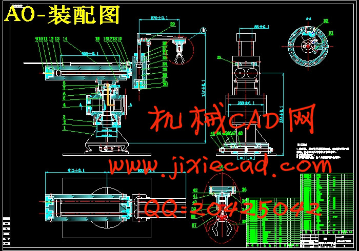
2.4工作原理 14
第3章相关零件的设计计算 15
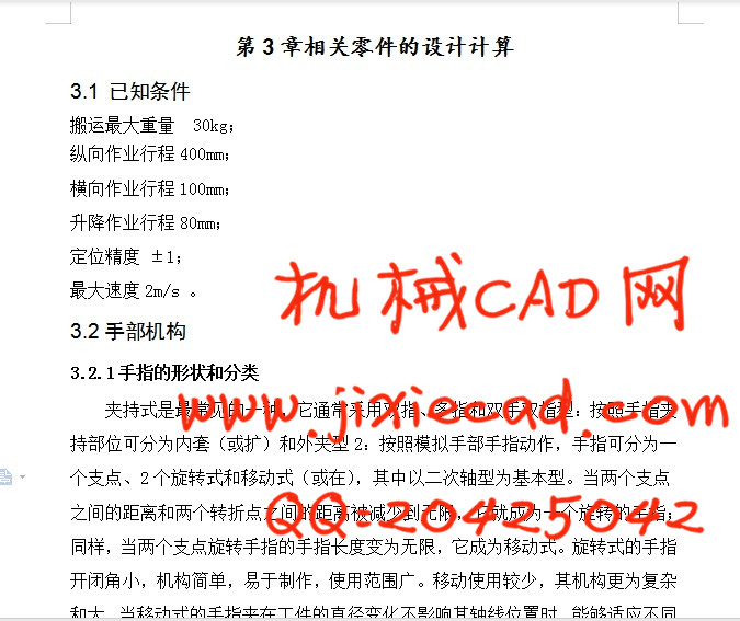
3.1 已知条件 15
3.2手部机构 15
3.2.1手指的形状和分类 15
3.2.2设计时考虑的几个问题 15
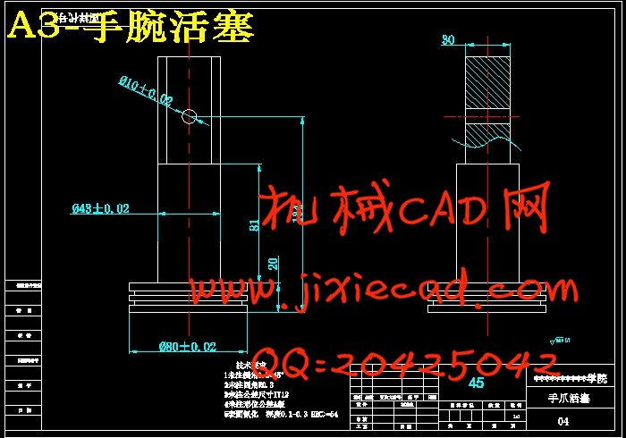
3.2.3手部夹紧液压缸的设计 16
3.2手抓液压缸的尺寸设计与校核 17
3.3纵向液压缸的尺寸设计与校核 18
3.3.1 尺寸设计 18
3.3.2 尺寸校核 19
3.4升降液压缸的尺寸设计与校核 19
3.6 上料机械手机体的设计计算 19
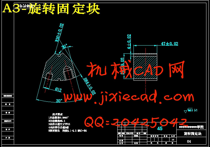
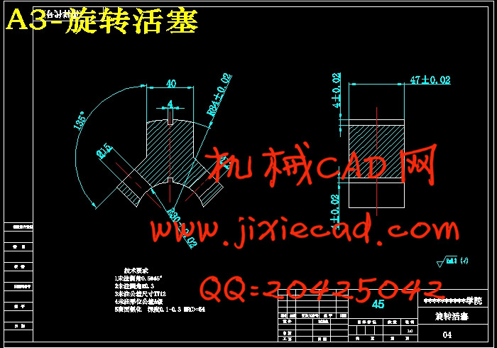
3.6.1上料机械手机体转动时所需的驱动力矩 19
3.6.2 上料机械手机体回转缸的尺寸及其校核 22
第4章 液压系统的设计 25
4.1确定液压系统的主要参数 25
4.1.1载荷的组成与计算: 25
4.1.2初选系统压力 27
4.1.3计算液压缸的主要结构尺寸 28
4.1.4确定液压泵的参数 30
4.2液压缸主要零件结构、材料及技术要求 32
4.2.1缸体 32
4.2.2活塞 33
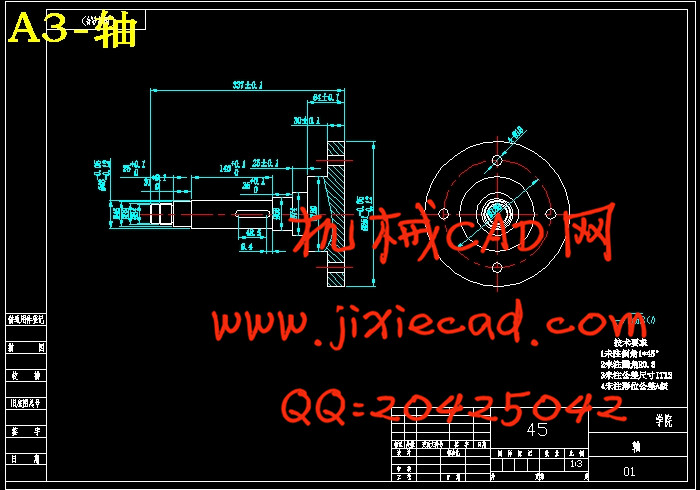
4.2.3活塞杆 34
4.2.4活塞杆的导向、密封和防尘 35
4.2.5液压缸的排气装置 35
4.2.6液压缸安装联接部分的型式及尺寸 36
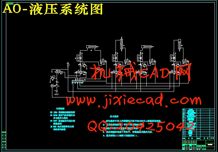
4.3绘制液压系统原理图 36
总结与展望 39
致谢 41
参考文献 42