设计简介
中文摘要
组合机床是以通用部件为基础,配以按工件特定外形和加工工艺设计的专用部件和夹具,组成的半自动或自动专用机床。
设计组合机床之前需要零件分析 ,了解所欲加工零件的加工特点,精度和技术要求。
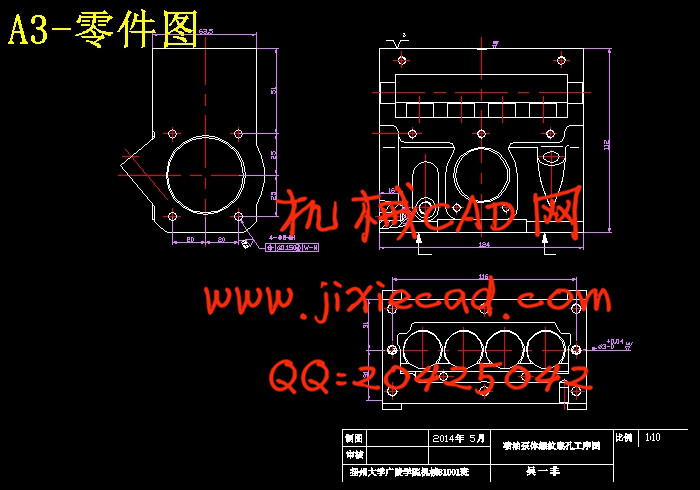
然后制定工艺方案,必须计算分析被加工零件图,并深入了解零件的形状、大小、材料、硬度、刚度,加工部位的结构特点加工精度,表面粗糙度,以及定位,夹紧方法,工艺过程,所采用的刀具及切削用量,生产率要求等等。最终确定零件在组合机床上完成加工时的定位基准以及零件的加工工艺方案。
各方面准备做好以后进行组合机床设计——三图一卡设计,包括零件图绘制零件工序图、零件加工示意图、机床尺寸联系图、制机床生产率计算卡。
最后根据主轴结构形式和动力设计并设计主传动系统总体结构 ,进行主轴箱设计 ,确定齿轮齿数、齿轮直径、齿轮中心距、轴、轴承等等,绘制主轴箱草图。
关键字:组合机床,工艺,三图一卡,主轴箱
Abstract
Modular machine tool is based on common components, with special components designed according to workpiece specific shape and process and fixture, consisting of semi-automatic or automatic machine tool.
Analysis on parts is needed before the design of modular machine tool, understanding to the components processing features, precision and technology.
Then the process plan, we must analysis the parts to be machined, and a deeper understanding of parts of the shape, size, material, hardness, stiffness, structural characteristics of processing parts of the machining accuracy, surface roughness, and the positioning, clamping method, technological process, the cutter and cutting parameter, productivity and so on. Ultimately determine the parts processed in modular machine when the locating datum and machining process.
All ready to do a good job after lathe design -- the three charts card design, including the parts drawing process map parts, machining sketch, machine size contact map, making machine productivity calculation card.
Finally, according to the main structure and dynamic design and structure design of main transmission system, the design of spindle box, determine the number of gear teeth, gear, gear center distance, shaft diameter, bearing, spindle box sketch drawing.
Keywords: combination of machine tools, process, three charts card, spindle box
目录
中文摘要…………………………………………………………………………… Ⅰ
Abstract…………………………………………………………………………… Ⅱ
第一章 概述…………………………………………………………………………1
1.1 组合机床概述…………………………………………………………………… 1
1.2 组合机床的发展………………………………………………………………… 1
1.3 组合机床的特点………………………………………………………………… 1
1.4 组合机床的设计方法…………………………………………………………… 2
1.5 组合机床设计的目的、要求…………………………………………………… 3
1.5.1 设计的目的…………………………………………………………………… 3
1.5.2 设计要求……………………………………………………………………… 3
1.6 本课题任务的内容和要求……………………………………………………… 4
第二章 组合机床方案的制定……………………………………………………5
2.1制定工艺方案…………………………………………………………………… 5
2.1.1被加工零件的特点…………………………………………………………… 5
2.1.2被加工零件的加工精度……………………………………………………… 5
2.1.3加工孔的主要技术要求……………………………………………………… 5
2.1.4定位基准及夹紧点的选择…………………………………………………… 5
2.1.5确定工艺方案的原则及注意问题…………………………………………… 5
2.1.6零件的生产批量……………………………………………………………… 7
第三章 确定切削用量及选择刀具…………………………………………… 9
3.1选择切削用量…………………………………………………………………… 9
3.2确定切削力、切削扭矩、切削功率…………………………………………… 10
3.3选择刀具结构…………………………………………………………………… 11
第四章 钻孔组合机床总设计“三图一卡”的编制……………………… 13
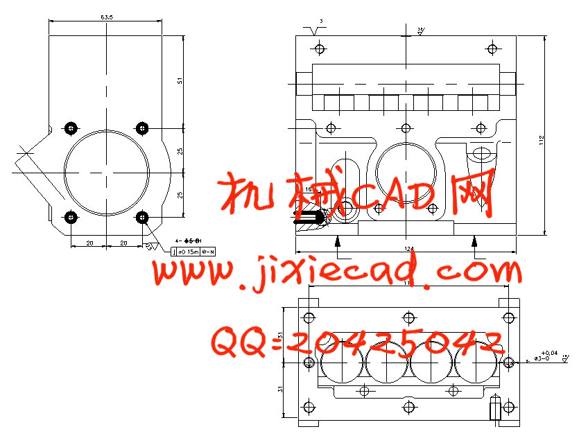
4.1被加工零件工序图……………………………………………………………… 13
4.1.1被加工零件工序图的作用及内容 ………………………………………… 13
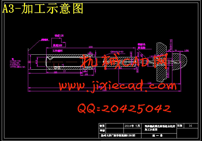
4.2加工示意图……………………………………………………………………… 14
4.2.1加工示意图的作用和内容…………………………………………………… 14
4.2.2绘制加工示意图之前的有关计算…………………………………………… 14
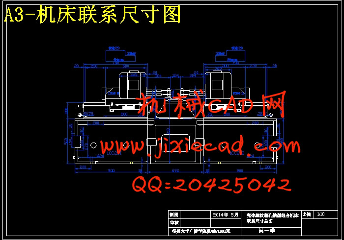
4.3机床联系尺寸图………………………………………………………………… 17
4.3.1联系尺寸图的作用和内容…………………………………………………… 17
4.3.2选用动力部件………………………………………………………………… 17
4.3.3配套支承部件的选用………………………………………………………… 19
4.3.4确定装料高度………………………………………………………………… 20
4.3.5确定多轴箱轮廓尺寸………………………………………………………… 20
4.4生产率计算卡…………………………………………………………………… 21
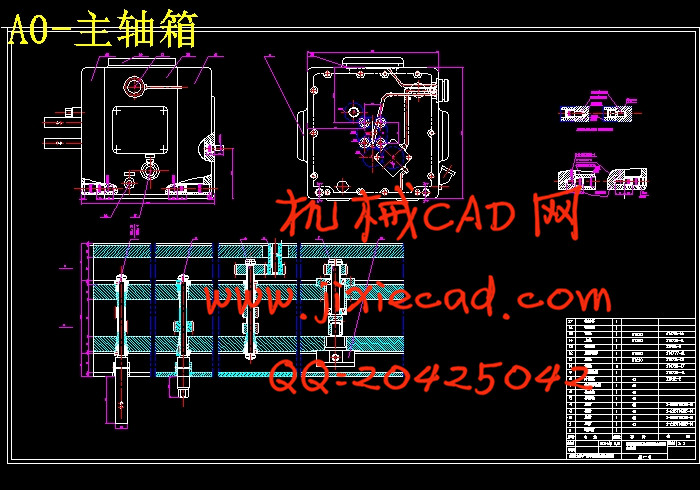
第五章 多轴箱的设计………………………………………………………… 19
5.1 主轴箱的设计步骤和内容…………………………………………………… 24
5.1.1 主轴箱所需动力的计算…………………………………………………… 24
5.1.2 主轴箱传动设计…………………………………………………………… 25
5.1.3 拟定主轴箱传动系统. …………………………………………………… 26
5.2 轴的具体设计……………………………………………………………………28
5.3传动零件的校核………………………………………………………………… 31
5.4绘制传动系统图………………………………………………………………… 35
第六章 工作总结和展望……………………………………………………… 36
参考文献……………………………………………………………………………38
致 辞……………………………………………………………………………… 39
附 录…………………………………………………………………………………40
组合机床是以通用部件为基础,配以按工件特定外形和加工工艺设计的专用部件和夹具,组成的半自动或自动专用机床。
设计组合机床之前需要零件分析 ,了解所欲加工零件的加工特点,精度和技术要求。
然后制定工艺方案,必须计算分析被加工零件图,并深入了解零件的形状、大小、材料、硬度、刚度,加工部位的结构特点加工精度,表面粗糙度,以及定位,夹紧方法,工艺过程,所采用的刀具及切削用量,生产率要求等等。最终确定零件在组合机床上完成加工时的定位基准以及零件的加工工艺方案。
各方面准备做好以后进行组合机床设计——三图一卡设计,包括零件图绘制零件工序图、零件加工示意图、机床尺寸联系图、制机床生产率计算卡。
最后根据主轴结构形式和动力设计并设计主传动系统总体结构 ,进行主轴箱设计 ,确定齿轮齿数、齿轮直径、齿轮中心距、轴、轴承等等,绘制主轴箱草图。
关键字:组合机床,工艺,三图一卡,主轴箱
Abstract
Modular machine tool is based on common components, with special components designed according to workpiece specific shape and process and fixture, consisting of semi-automatic or automatic machine tool.
Analysis on parts is needed before the design of modular machine tool, understanding to the components processing features, precision and technology.
Then the process plan, we must analysis the parts to be machined, and a deeper understanding of parts of the shape, size, material, hardness, stiffness, structural characteristics of processing parts of the machining accuracy, surface roughness, and the positioning, clamping method, technological process, the cutter and cutting parameter, productivity and so on. Ultimately determine the parts processed in modular machine when the locating datum and machining process.
All ready to do a good job after lathe design -- the three charts card design, including the parts drawing process map parts, machining sketch, machine size contact map, making machine productivity calculation card.
Finally, according to the main structure and dynamic design and structure design of main transmission system, the design of spindle box, determine the number of gear teeth, gear, gear center distance, shaft diameter, bearing, spindle box sketch drawing.
Keywords: combination of machine tools, process, three charts card, spindle box
目录
中文摘要…………………………………………………………………………… Ⅰ
Abstract…………………………………………………………………………… Ⅱ
第一章 概述…………………………………………………………………………1
1.1 组合机床概述…………………………………………………………………… 1
1.2 组合机床的发展………………………………………………………………… 1
1.3 组合机床的特点………………………………………………………………… 1
1.4 组合机床的设计方法…………………………………………………………… 2
1.5 组合机床设计的目的、要求…………………………………………………… 3
1.5.1 设计的目的…………………………………………………………………… 3
1.5.2 设计要求……………………………………………………………………… 3
1.6 本课题任务的内容和要求……………………………………………………… 4
第二章 组合机床方案的制定……………………………………………………5
2.1制定工艺方案…………………………………………………………………… 5
2.1.1被加工零件的特点…………………………………………………………… 5
2.1.2被加工零件的加工精度……………………………………………………… 5
2.1.3加工孔的主要技术要求……………………………………………………… 5
2.1.4定位基准及夹紧点的选择…………………………………………………… 5
2.1.5确定工艺方案的原则及注意问题…………………………………………… 5
2.1.6零件的生产批量……………………………………………………………… 7
第三章 确定切削用量及选择刀具…………………………………………… 9
3.1选择切削用量…………………………………………………………………… 9
3.2确定切削力、切削扭矩、切削功率…………………………………………… 10
3.3选择刀具结构…………………………………………………………………… 11
第四章 钻孔组合机床总设计“三图一卡”的编制……………………… 13
4.1被加工零件工序图……………………………………………………………… 13
4.1.1被加工零件工序图的作用及内容
4.2加工示意图……………………………………………………………………… 14
4.2.1加工示意图的作用和内容…………………………………………………… 14
4.2.2绘制加工示意图之前的有关计算…………………………………………… 14
4.3机床联系尺寸图………………………………………………………………… 17
4.3.1联系尺寸图的作用和内容…………………………………………………… 17
4.3.2选用动力部件………………………………………………………………… 17
4.3.3配套支承部件的选用………………………………………………………… 19
4.3.4确定装料高度………………………………………………………………… 20
4.3.5确定多轴箱轮廓尺寸………………………………………………………… 20
4.4生产率计算卡…………………………………………………………………… 21
第五章 多轴箱的设计………………………………………………………… 19
5.1 主轴箱的设计步骤和内容…………………………………………………… 24
5.1.1 主轴箱所需动力的计算…………………………………………………… 24
5.1.2 主轴箱传动设计…………………………………………………………… 25
5.1.3 拟定主轴箱传动系统. …………………………………………………… 26
5.2 轴的具体设计……………………………………………………………………28
5.3传动零件的校核………………………………………………………………… 31
5.4绘制传动系统图………………………………………………………………… 35
第六章 工作总结和展望……………………………………………………… 36
参考文献……………………………………………………………………………38
致 辞……………………………………………………………………………… 39
附 录…………………………………………………………………………………40