设计简介
摘要
组合机床是根据工件需要,以大量通用部件为基础,配以少量专用部件组成的一种高效专用机床.它主要用于棱体类零件和复杂件的孔面加工,其生产率高.因为工序集中,可多面,多位置,多轴,多刀同时自动加工.加工精度稳定,研制周期短,便于设计,制造和使用维护成本低,因此通用化,系列化,标准化程度高,通用零件占70%-80%.自动化程度高,劳动强度低.配置灵活,机床易于改造,产品或工艺变化时,通用部件一般还可以重复利用.其在汽车、拖拉机、柴油机、军工等轻工行业大批大量生产中已获得广泛使用,一些中小批量生产的企业,如机床、机车、工程机械等制造业中也广泛使用.
关键词:组合机床 孔 改造
ABSTRACT
The aggregate machine-tool is according to the work piece need, take the massive general parts as the foundation, matches one kind of highly effective special purpose machine which composes by the few special-purpose parts. It mainly uses in bank or ridge between fields the body class components and the duplicate miscellaneous items hole surface processing, its productivity is high. Because the working procedure is centralized, but multi-surface, multiposition, multiple spindle, at the same time multi-knives automatic processing. The processing precision is stable, the development cycle is short, is advantageous for the design, the manufacture and the use maintenance cost is low, therefore the universalization, the seriation, the standardized degree is high, the common parts account for 70%-80%. automaticities to be high, the labor intensity is low. Disposes nimbly, the engine bed easy to transform, when product or craft change, the general part also may generally the reuse. It in light industry profession large quantities of mass productions and so on automobile, tractor, diesel engine, war industry has obtained the widespread use, some small batch production enterprise, like manufacturing industries and so on in engine bed, locomotive, project machinery also widely uses.
Key word: Aggregate machine-tool hole transformation
目 录
摘要 I
ABSTRACT II
第1章 前言
 1
1
第2章 工件工艺加工流程 3
2.1 总体方案论证 3
2.2 确定切削用量及选择刀具 4
2.2.1 选择切削用量 4
第3章 工艺规程设计 7
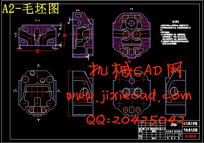
·3.1 确定毛坯的制造形式,加工余量,工序尺寸及毛坯尺寸 7
3.2 基准的选择 9
3.2.1精基准的选择 9
3.2.2粗基准的选择 10
3.3 工艺路线的拟订及工艺方案的分析 10
3.4 加工工序的设计 11
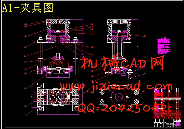
第4章 夹具设计 34
4.1定位基准的选择 34
4.2切削力与夹紧力的计算 34
4.3支承部件的设计 35
4.4夹具设计及操作的简要说明 36
第5章 主轴箱设计 37
5.1组合机床主轴箱设计 37
5.1.1 主轴结构型式的选择 38
5.1.2 主轴直径和齿轮模数的确定 39
第6章 主轴箱传动系统的设计与计算 40
6.1主轴箱传动系统的设计与计算 40
6.2 确定传动轴位置及齿轮齿数 40
A.由各主轴几驱动轴转速求驱动轴到各主轴之间的传动比 40
6.3齿轮的校核 41
设计准则 41
按齿面接触疲劳强度设计 41
第7章 样机试验测试 44
7.1 组合机床空运转试验 44
7.1.1 样机试验要求 44
7.1.2 样机试验结果 44
7.2 组合机床铣削试验 44
7.2.1 组合机床试验过程 44
7.3 进行精度测试 44
第8章 结论 46
参考文献 47
致 谢 48
组合机床是根据工件需要,以大量通用部件为基础,配以少量专用部件组成的一种高效专用机床.它主要用于棱体类零件和复杂件的孔面加工,其生产率高.因为工序集中,可多面,多位置,多轴,多刀同时自动加工.加工精度稳定,研制周期短,便于设计,制造和使用维护成本低,因此通用化,系列化,标准化程度高,通用零件占70%-80%.自动化程度高,劳动强度低.配置灵活,机床易于改造,产品或工艺变化时,通用部件一般还可以重复利用.其在汽车、拖拉机、柴油机、军工等轻工行业大批大量生产中已获得广泛使用,一些中小批量生产的企业,如机床、机车、工程机械等制造业中也广泛使用.
关键词:组合机床 孔 改造
ABSTRACT
The aggregate machine-tool is according to the work piece need, take the massive general parts as the foundation, matches one kind of highly effective special purpose machine which composes by the few special-purpose parts. It mainly uses in bank or ridge between fields the body class components and the duplicate miscellaneous items hole surface processing, its productivity is high. Because the working procedure is centralized, but multi-surface, multiposition, multiple spindle, at the same time multi-knives automatic processing. The processing precision is stable, the development cycle is short, is advantageous for the design, the manufacture and the use maintenance cost is low, therefore the universalization, the seriation, the standardized degree is high, the common parts account for 70%-80%. automaticities to be high, the labor intensity is low. Disposes nimbly, the engine bed easy to transform, when product or craft change, the general part also may generally the reuse. It in light industry profession large quantities of mass productions and so on automobile, tractor, diesel engine, war industry has obtained the widespread use, some small batch production enterprise, like manufacturing industries and so on in engine bed, locomotive, project machinery also widely uses.
Key word: Aggregate machine-tool hole transformation
目 录
摘要 I
ABSTRACT II
第1章 前言
第2章 工件工艺加工流程 3
2.1 总体方案论证 3
2.2 确定切削用量及选择刀具 4
2.2.1 选择切削用量 4
第3章 工艺规程设计 7
·3.1 确定毛坯的制造形式,加工余量,工序尺寸及毛坯尺寸 7
3.2 基准的选择 9
3.2.1精基准的选择 9
3.2.2粗基准的选择 10
3.3 工艺路线的拟订及工艺方案的分析 10
3.4 加工工序的设计 11
第4章 夹具设计 34
4.1定位基准的选择 34
4.2切削力与夹紧力的计算 34
4.3支承部件的设计 35
4.4夹具设计及操作的简要说明 36
第5章 主轴箱设计 37
5.1组合机床主轴箱设计 37
5.1.1 主轴结构型式的选择 38
5.1.2 主轴直径和齿轮模数的确定 39
第6章 主轴箱传动系统的设计与计算 40
6.1主轴箱传动系统的设计与计算 40
6.2 确定传动轴位置及齿轮齿数 40
A.由各主轴几驱动轴转速求驱动轴到各主轴之间的传动比 40
6.3齿轮的校核 41
设计准则 41
按齿面接触疲劳强度设计 41
第7章 样机试验测试 44
7.1 组合机床空运转试验 44
7.1.1 样机试验要求 44
7.1.2 样机试验结果 44
7.2 组合机床铣削试验 44
7.2.1 组合机床试验过程 44
7.3 进行精度测试 44
第8章 结论 46
参考文献 47
致 谢 48