设计简介
摘 要
随着自动化应用的逐步提高,组合机床越来越多的出现在现代工厂中,组合机床是以通用部件为基础,配以工件特定外形和加工工艺设计的专用部件和夹具,组成的半自动或自动专用机床。它一般采用多轴,多刀,多工序,多面或多工位同时加工的方式,生产效率比通用机床高几倍至几十倍。由于通用部件已经标准化合系列化,可根据需要灵活配置,能缩短设计和制造周期。因此,组合机床兼有低成本和高效率的优点,在大批量生产中得到广泛应用,并可用以组成自动生产线。本次设计为皮套圈座钻孔专用机床,同时完成3个孔的加工。主要有以下几个方面:
1.方案的制定,根据提供的零件图,通过相关材料分析制定可行性方案并拟定加工工艺规程;
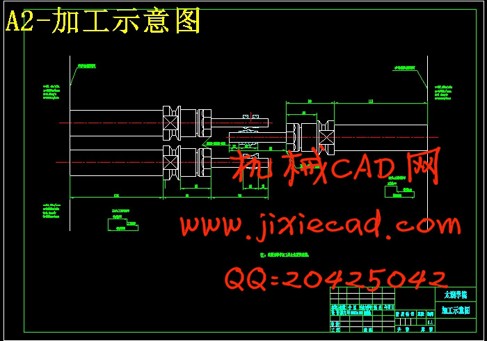
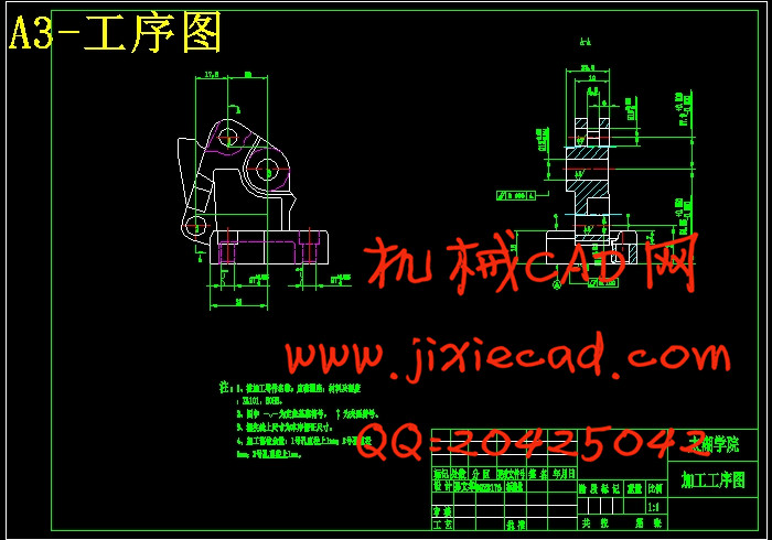
2.“三图一卡”:工序图、加工示意图、尺寸联系图的绘制以及生产率计算卡的计算,根据要求设计图纸;
3.主轴箱结构的设计,包括动力系统、传动系统的制定,轴的设计,齿轮的设计,轴承的选择,润滑系统的制定;
4.零件图的绘制,包括轴、齿轮;
5.说明书的撰写。
关键词:组合机床;组合机床;三图一卡
Abstract
With increasing automation applications, combined machine tool more and more appear in modern factories, the combination of more occasions based on general parts, match with workpiece specific shape and process design of special components and fixtures, composed of semi-automatic or automatic special machine. It usually adopts the multiaxial, knife, processes, and multi-faceted or multistage and processing, production efficiency than general machine high several times or more. Due to the common parts have standard series, can according to the combined flexible configuration, can shorten the cycle of design and manufacture. Therefore, the combination machine has the advantages of low cost and high efficiency, in large, mass production is widely used, and the automatic production line can be used to composition.The design for the leather seat drilling machine, the processing at the same time to complete the 3 hole.This design mainly in the following aspects:
1. According to the formulation of programmes, providing the parts drawing through relevant material analysis, the feasibility plan and plan formulated processing procedures;
2. "three graph one card" : process graph, processing schemes, size contact drawing and productivity calculation according to requirements of calculation, card design drawings;
3. Spindle box structure design, including power system and transmission system, the design of the formulation of shaft, the gear design, bearing the formulation of choice, lubricating system;
4. Component drawing, including shaft, gear;
5. Written instructions.
Key words: Unit built machine tool; Spindle box; Three diagram a card
目 录
摘 要 III
Abstract IV
目 录 V
1 绪论 1
1.1 课题的来源及意义 1
1.2 组合机床及特点 1
1.3 国内外该研究技术现状 1
2 组合机床总体方案设计 2
2.1 组合机床的设计步骤 2
2.2 编制工艺规程的原始资料 2
2.2.1 被加工零件图一张 2
2.2.2 零件机械加工工艺路线的拟定 4
2.2.3 工序的加工余量及切削刀具的选择 5
2.2.4 切削刀具的选择 5
2.3 组合机床切削用量选择及计算 5
2.4 确定机床的配置形式 7
2.5 “三图”的编制 8
2.5.1 被加工零件工序图 8
2.5.2 加工示意图 9
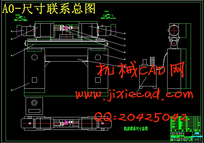
2.5.3 机床联系尺寸总图 11
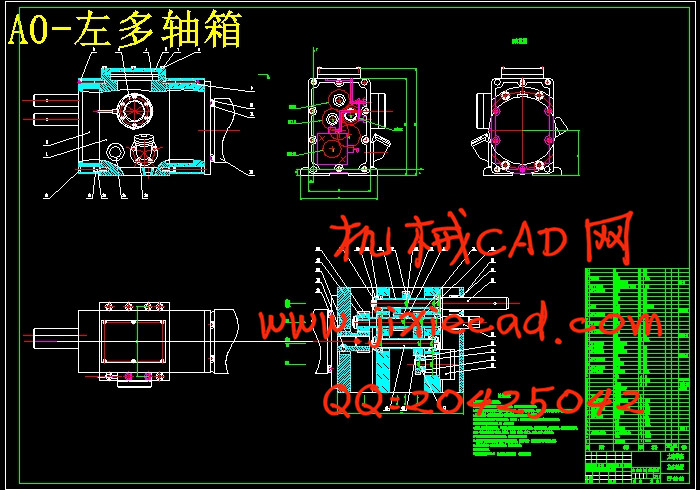
3 左多轴箱的设计 13
3.1电动机的选择 13
3.2 绘制多轴箱设计原始依据图 13
3.3 确定主轴结构型式及齿轮模数 14
3.4 多轴箱传动系统设计 14
3.4.1 拟定传动路线 14
3.4.2 确定传动轴位置及齿轮齿数 15
3.4.3 绘制传动系统图 16
3.5 绘制多轴箱总图 16
4 右多轴箱设计 21
4.1 电动机的选择 21
4.2 绘制多轴箱设计原始依据图 21
4.3 确定主轴结构型式及齿轮模数 21
4.4 多轴箱传动系统设计 22
4.4.1 拟定传动路线 22
4.4.2 确定传动轴位置及齿轮齿数 23
4.4.3 绘制传动系统图 24
4.5 液压滑台结构的设计 25
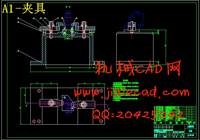
5 夹具的设计 26
5.1 定位基准的选择: 26
5.2 夹紧方案的确定 26
5.3 夹紧力的计算 26
5.4 定位误差分析 26
5.5 组合机床“一卡”的编制 27
6 结论 29
6.1 结论 29
6.2 不足之处及未来展望 29
致 谢 30
参考文献: 31