设计简介
摘 要
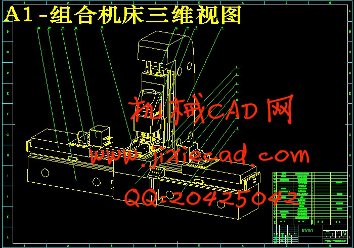
本文的设计题目是减速器箱体卧式钻孔专用组合机床结构设计。设计任务是制定减速器箱体结合件的加工工艺、组合钻孔工序的工装设计、液压控制系统设计、组合机床设计。在工艺制定过程中,通过生产批量的分析确定减速器箱体结合件的加工方案,并寻求最佳的工艺方案,借此说明了工艺在生产过程中的重要性;在组合钻孔工序的工装设计过程中,结合实例,介绍了对孔的加工精度进行了探讨;在液压控制系统设计过程中,以三面钻孔组合机床为对象,依据液压系统设计的基本原理,拟出合理的液压系统图。通过系统主要参数的计算确定了液压元件的规格;在组合机床设计过程中,结合具体实例和设计经验, 阐述了通用件(如液压滑台,动力箱等)的选取及专用部件(如主轴箱)的设计计算。使得设计的组合机床达到效率最大化。
关键词:组合机床 工艺方案 钻孔工序 液压传动
Abstract
This topic is the design of gear box special combination of horizontal drilling machine structure design The design task is to develop reducer box with pieces of the processing technology, combined drilling process tooling design, hydraulic control system design, machine design portfolio.In the course of the development process, through the production of bulk analysis reducer box with the processing of the programme and seek the best technology programme, to take this description of the process in the importance of the production process;In the composition of the drilling process tooling design process, with examples, introduced a ixture design methods, especially for precision-processing were discussed;In the hydraulic control system design process, to three drilling machine for the composition of objects, the hydraulic system based on the basic principles of design, to be a reasonable map of the hydraulic system.Through the system of calculating the main parameters determining the specifications of the hydraulic components in the composition of machine design process, with specific examples and design experience, expounded the common parts (such as hydraulic slider, the driving force for me, and so on) select and exclusive parts (such as Multi-axle box) the design and calculation.
Key Words: Machine toll;Process plan;Drilling process;Hydraulic
目录
摘 要
Abstract
绪论1
第一章 组合机床简介1
1.1组合机床的历史及发展情况 1
1.2本文的主要内容及设计步骤 2
第二章 工艺方案的拟定 4
2.1减速器箱体零件的工艺技术分析 4
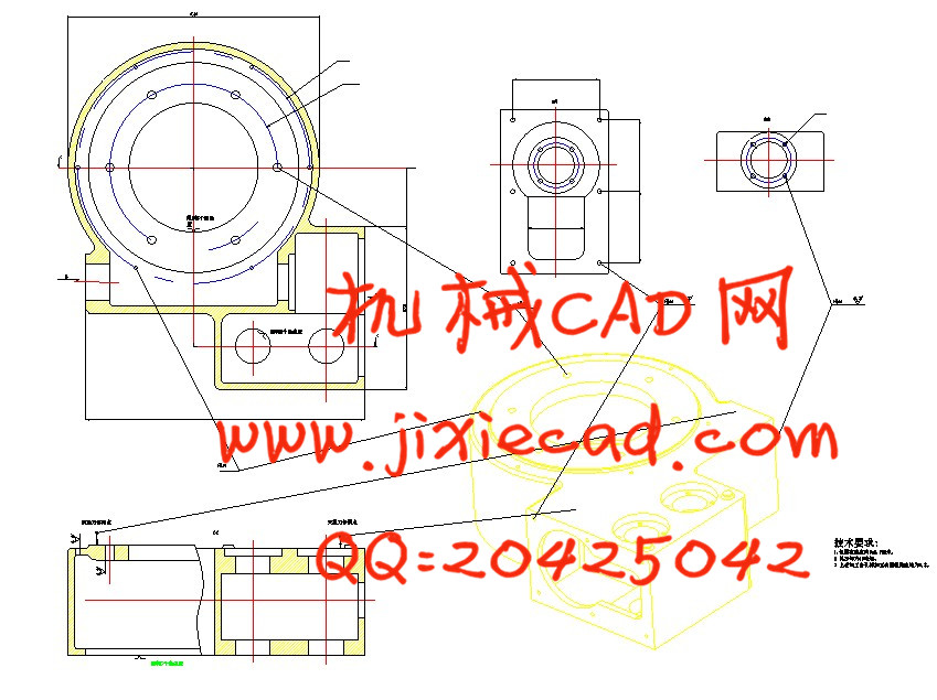
2.2减速器零件工序图 5
第三章 组合机床的总体设计 7
3.1组合机床自动线的组成和分类 7
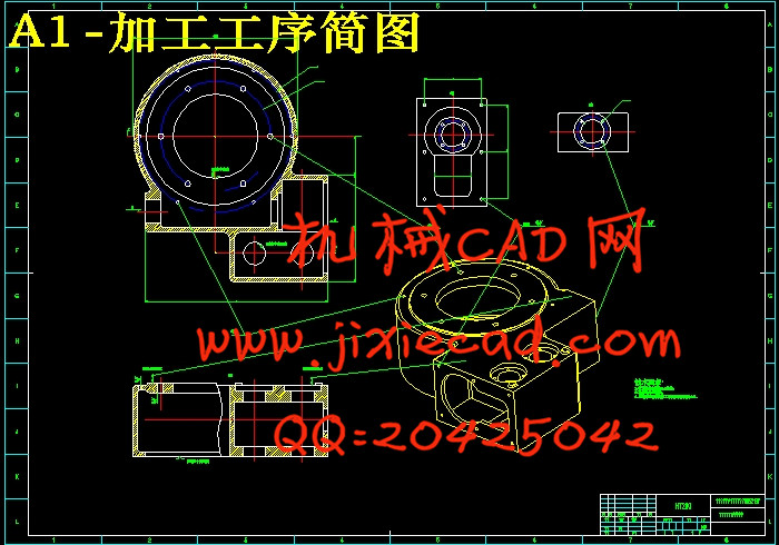
3.2被加工工件工序简图 7
3.2.1被加工零件工序简图的作用与内容 7
3.2.2 绘制被加工零件图的规定及注意事项: 8
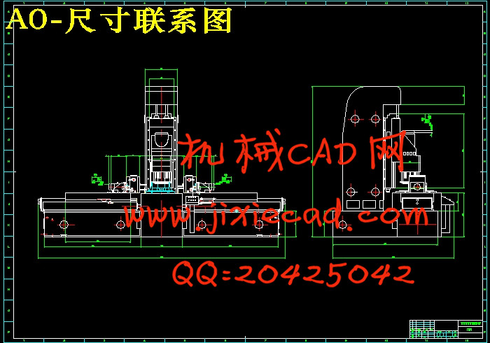
3.3 加工示意图 8
3.3.1 加工示意图的作用和内容: 8
3.3.2选择刀具、导向及有关计算 8
3.4合机床通用部件的选用 9
3.4.1动力滑台的选用 10
3.4.2支撑部件的选用 11
3.4.3动力部件的选用 13
第四章 立式多轴箱设计 16
4.1引言 16
4.2主体设计 16
4.2.1多轴箱盖与箱体的选用 16
4.2.2通用主轴类型的选用 16
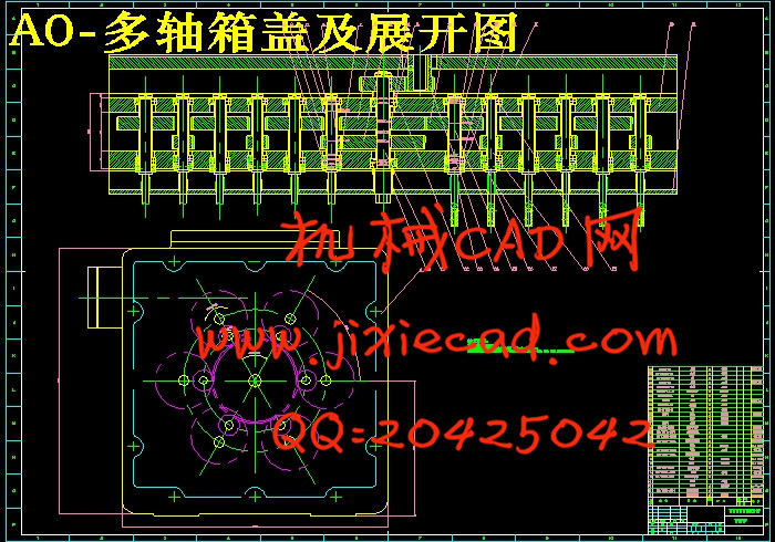
4.2.3多轴箱原始设计图 16
4.3传动轴、主轴、齿轮的确定 17
4.3.1齿轮模数m的确定 17
4.3.2传动轴的选用 17
4.3.3主轴的选用 18
4.3.4多轴箱传动设计 18
4.3.5齿轮的校核 20
4.3.6键的校核 21
第五章 液压系统设计 23
5.1钻削进给液压系统设计 23
5.1.1作F-t与V-t图 23
5.1.2确定液压系统参数 24
5.1.3拟定液压系统图 25
第六章 组合机床PLC控制26
总结 31
参考文献 32
致 谢 33
Abstract
绪论1
第一章 组合机床简介1
1.1组合机床的历史及发展情况 1
1.2本文的主要内容及设计步骤 2
第二章 工艺方案的拟定 4
2.1减速器箱体零件的工艺技术分析 4
2.2减速器零件工序图 5
第三章 组合机床的总体设计 7
3.1组合机床自动线的组成和分类 7
3.2被加工工件工序简图 7
3.2.1被加工零件工序简图的作用与内容 7
3.2.2 绘制被加工零件图的规定及注意事项: 8
3.3 加工示意图 8
3.3.1 加工示意图的作用和内容: 8
3.3.2选择刀具、导向及有关计算 8
3.4合机床通用部件的选用 9
3.4.1动力滑台的选用 10
3.4.2支撑部件的选用 11
3.4.3动力部件的选用 13
第四章 立式多轴箱设计 16
4.1引言 16
4.2主体设计 16
4.2.1多轴箱盖与箱体的选用 16
4.2.2通用主轴类型的选用 16
4.2.3多轴箱原始设计图 16
4.3传动轴、主轴、齿轮的确定 17
4.3.1齿轮模数m的确定 17
4.3.2传动轴的选用 17
4.3.3主轴的选用 18
4.3.4多轴箱传动设计 18
4.3.5齿轮的校核 20
4.3.6键的校核 21
第五章 液压系统设计 23
5.1钻削进给液压系统设计 23
5.1.1作F-t与V-t图 23
5.1.2确定液压系统参数 24
5.1.3拟定液压系统图 25
第六章 组合机床PLC控制26
总结 31
参考文献 32
致 谢 33