设计简介
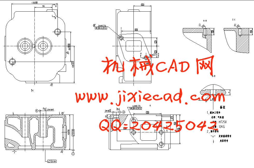
基于三维的柴油机气缸盖组合钻床总体及后主轴箱设计
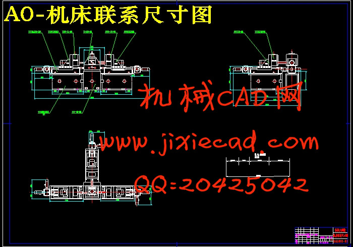
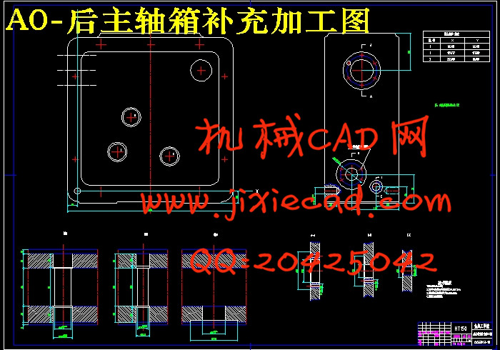
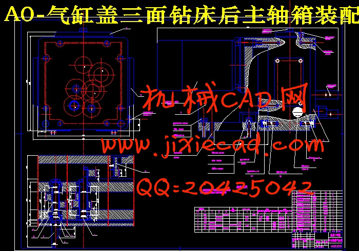
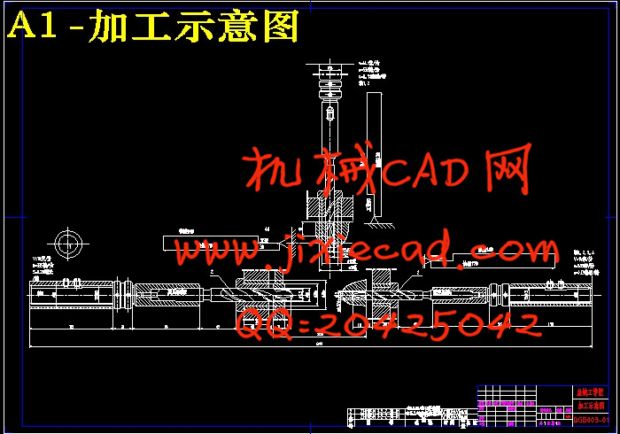
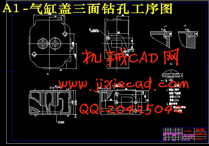
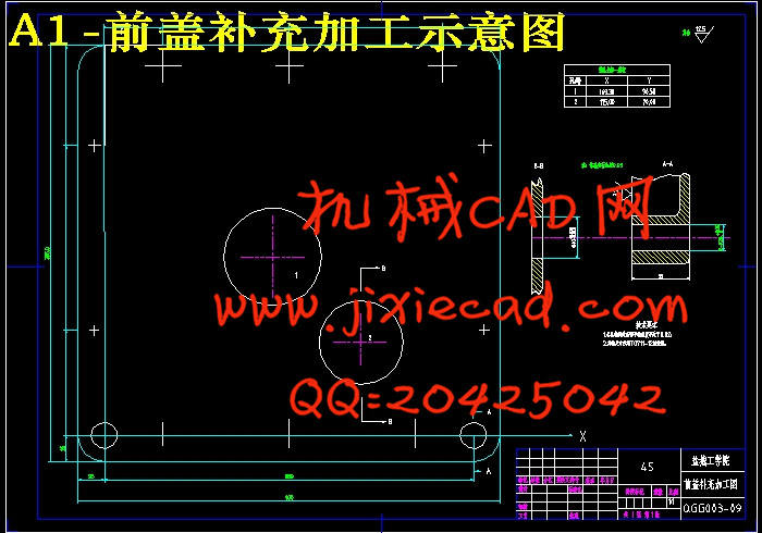
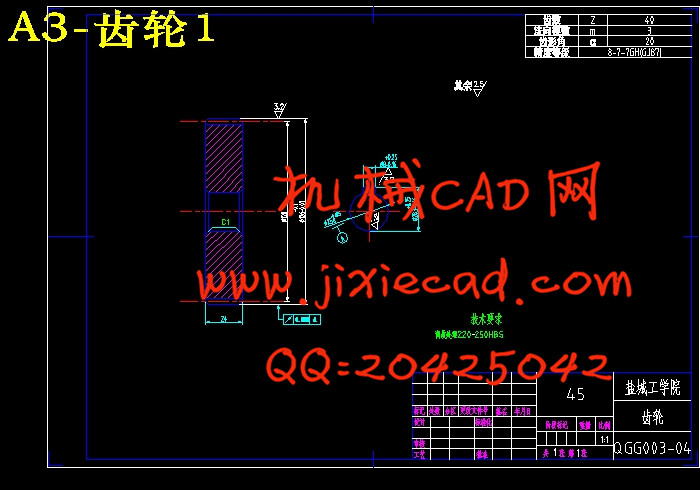
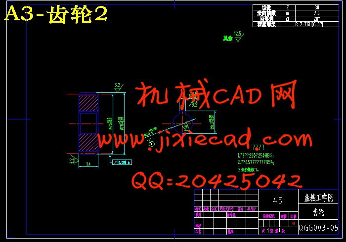
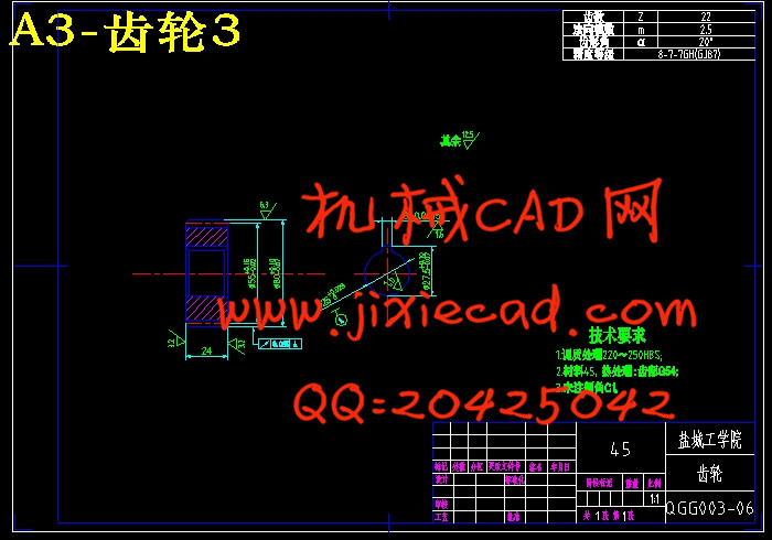
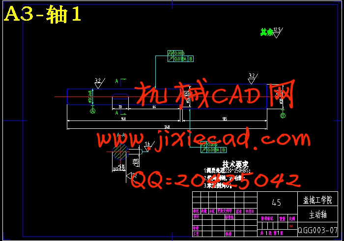
摘 要:组合机床是根据工件加工需要,以大量通用部件为基础,配以少量专用部件组成的一以及种高效的专用机床。组合机床一般采用多轴、多刀、多工序、多面或多工位同时加工的方法,生产效率比通用机床高几倍至几十倍。本课题设计的是卧式三面钻孔组合钻床,来源于盐城市江淮动力集团。柴油机气缸盖是需要大量生产的零件,为了提高加工精度和生产效率,需要设计一种组合机床来改善柴油机气缸盖的加工情况。该设计的内容包括总体设计和后主轴箱设计。在总体设计中分析了被加工零件的加工工艺性,选择了加工的定位基准及加紧方案等,同时完成了“三图一卡”的绘制。在后主轴箱设计方面,首先确定绘制后主轴箱设计原始依据图,接着对主轴结构型式选择和动力的计算,然后对主轴箱传动系统进行设计与计算,在对后主轴箱中的传动轴直径和传动轴在箱体中的位置进行计算,最后对轴和齿轮的强度进行校核,绘制出主轴箱中传动轴坐标检查图。本组合机床效率高,成本低,加工精度高,操作使用方便,减轻了工人的劳动强度,提高了劳动生产率,满足了设计需要。
关键词:气缸盖;钻孔;组合机床;主轴箱
Based on the 3D engine cylinder head and the overall portfolio after the drilling spindle box desig
Abstract: The combination of machine parts processing is based on need, to a large number based on common components, supported by a small number of dedicated components of a highly efficient and dedicated machine.The general composition of multi-axis machine tools, multi-tool, multi-process, multi-faceted public place or method of processing at the same time, production of high-efficient than GM machine several times to 10 times. This design is the subject of horizontal drilling combination of drilling on three sides, the impetus comes from Yancheng Jianghuai Group. Diesel engine cylinder head is the need to mass-produced parts, in order to increase production efficiency and accuracy of processing, machine tools needed to design a combination of diesel engine cylinder head to improve the processing conditions. The design will include design and post-spindle box design. In the overall design of the processing parts of the processing technology, select the location of the processing base and intensify their programmes, and completed a "three-card plans a" mapping. After the spindle box in the design, the first set after drawing spindle box design based on the original map, then the main structure of the power and choice, then the spindle box drive system design and calculation, in the main shaft after me in the drive shaft diameter And the transmission shaft in the box in the location, the last of the gear shaft and the strength of Verification, to map out spindle box in the drive shaft inspection map coordinates. The combination of machine high efficiency, low cost, high-precision machining, easy operation, reducing the labor intensity of the workers, increased labor productivity, and meet the needs of the design.
Key words: cylinder head; bored; combination machine; Headstock
目 录
1绪论 1
2 零件加工工艺规程 3
2.1概述 3
2.2零件的作用 3
2.3 零件的工艺分析 3
2.4确定工艺方案的原则及注意问题 3
2.4.1粗、精加工分开原则 3
2.4.2工序集中与分散的原则 4
2.4.3制定工艺方案应注意的其它问题 5
2.5工艺规程的设计 5
2.5.1确定毛坯材料及尺寸 5
2.5.2定位基准的选择 5
2.5.3制定工艺路线 6
2.6工序尺寸的基本要求 7
2.7 确定切削用量和基本工时 8
2.8 切削用量的选择依据 22
2.8.1铣削 22
2.8.2钻孔 22
2.8.3扩孔和铰孔 23
2.8.机床精度及机床参数 23
2.9 各种加工工艺和加工方法 24
2.9.1平面加工工艺 24
2.9.3螺纹加工工艺 24
2.10常用工艺主要工序能达到的精度和表面粗糙度 24
2.10.1平面加工 24
2.10.2螺纹孔加工 25
3 专用夹具的设计 26
3.1 对铣床夹具体的要求 26
3.2 夹具体的毛坯结构 26
3.3夹具元件的选择与设计 26
3.4 专用夹具的设计步骤 27
3.5 绘制夹具总装配图 27
3.6 标注夹具总装配图上个部分尺寸和技术要求。 28
3.7 夹具公差配合的制订 28
3.7.1 制订夹具公差与技术条件的依据 28
3.7.2 制定夹具公差和技术条件的基本原则 28
3.8夹具公差的制订 29
3.9 夹具技术条件的制订 29
3.10夹具设计部分的计算 29
3.10.1基准的选择 29
3.10.2切削夹紧力的计算 29
3.10.3定位误差的分析 30
4 零件编码系统 33
4.1零件编码系统的概念 33
4.2零件分类编码系统的要求 34
4.3零件分类编码系统的设计和选择 34
4.4零件的分类成组技术 34
4.4.1编码分类法 34
4.4.2生产流程分析法 35
总结 38
致谢 39
参考文献 40
附录 41