设计简介
摘要
机械手作为一个代表整个工业的结合体,综合利用机电液三位一体的新系统,超越各自的性能,已经成为各行各业广泛应用的代表。
本文针对通用性压铸机机械手进行设计,涉及到机械手零部件的设计,回转机构,升降机构,以及液压系统的设计。 并进行液压系统的设计以及动作顺序表的设计,对回转油缸的设计和校对做出了详细的计算与分析。
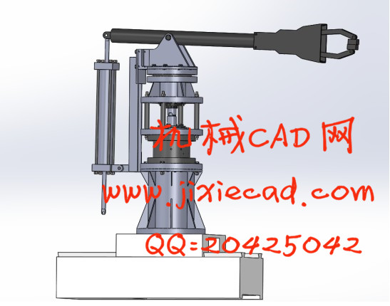
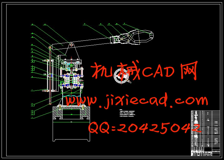
最后利用CAD与SolidWorks分别进行二位与三维设计,目的是更加直观的看到机械手工作的特性,能够参与到实际应用中。
关键词:机械手,浇注,液压系统
Abstract机械手作为一个代表整个工业的结合体,综合利用机电液三位一体的新系统,超越各自的性能,已经成为各行各业广泛应用的代表。
本文针对通用性压铸机机械手进行设计,涉及到机械手零部件的设计,回转机构,升降机构,以及液压系统的设计。 并进行液压系统的设计以及动作顺序表的设计,对回转油缸的设计和校对做出了详细的计算与分析。
最后利用CAD与SolidWorks分别进行二位与三维设计,目的是更加直观的看到机械手工作的特性,能够参与到实际应用中。
关键词:机械手,浇注,液压系统
As a combination of the whole industry, the manipulator has become a representative of the wide application of various industries.
In this paper, the design of the mechanical hand of the universal die-casting machine involves the design of the mechanical hand parts, the rotary mechanism, the lifting mechanism, and the hydraulic system design. The design of the hydraulic system and the design of the sequence table are carried out, and the design and proofreading of the rotary oil cylinder are calculated and analyzed in detail.
Finally, CAD and SolidWorks are used to perform two and three dimensional design respectively. The purpose is to see the characteristics of manipulator work more directly and to automate production.
Keywords: manipulator, pouring, hydraulic system.
目录
摘要 Ⅰ
Abstract Ⅱ
1 绪论 1
1.1国内外发展状况 1
1.2 机械手的组成 1
1.2.1执行机构 1
1.2.2驱动机构 2
1.2.3控制系统 4
1.3 应用机械手的意义 4
2 总方案设计 5
2.1原始数据 5
2.2 工作要求 5
2.3 系统组成 5
2.3.1工作原理 5
2.3.2工作过程: 5
2.3.4各个动作时间设定: 6
2.3.5液压系统原理图: 6
2.3.6液压系统的特点: 7
2.4 总体技术方案 7
2.4.1手部 8
3 手部结构设计 9
3.1 手部结构 9
3.1.1手指的形状和分类 9
3.1.2 设计时考虑的几个问题 9
3.2 手部夹紧液压缸的设计 10
3.2.1夹紧力的计算: 10
3.2.2夹紧缸的设计与计算: 11
4 手腕结构设计 14
4.1 手腕的自由度 14
4.2 手腕的驱动力矩的分析 14
4.2.1手腕转动时所需的驱动力矩 14
5 升降,回转液压缸的尺寸设计与校核 17
5.1 平衡装置 17
5.2 手臂升降液压缸的尺寸设计与校核 17
5.2.1概述: 17
5.2.2分类: 17
5.2.3结构: 17
5.2.4工作原理: 17
5.2.5结构图: 18
5.2.6本设计选用液压缸类型: 18
5.3 尺寸设计 18
5.4 尺寸校核 19
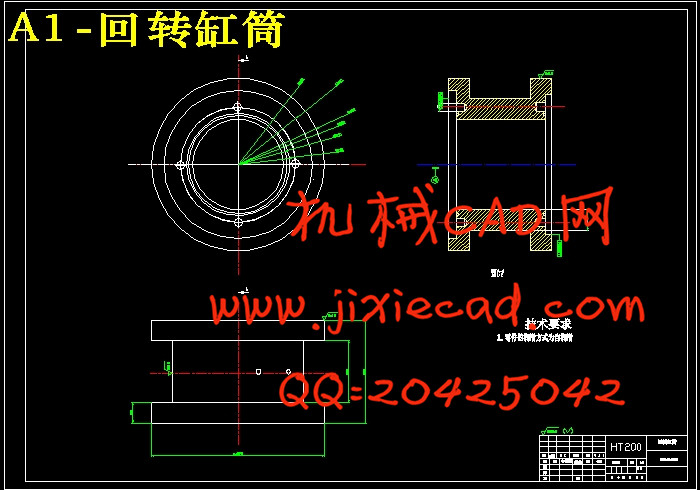
5.5 手臂回转液压缸的尺寸设计与校核 19
5.5.1工作特点: 19
5.5.2分类: 19
5.5.3单叶片结构: 20
5.5.4工作原理: 20
5.5.5设计计算: 20
5.6 尺寸设计 20
5.7 尺寸校核 21
6 总体装配图 23
结论: 24
参考文献: 25
致谢 27