设计简介
摘要
变速器是汽车的重要组成部分,它可以在较大范围内改变发动机的输出转速和转矩,使发动机在最佳的工作状态满足汽车在不同行驶状况下的工作要求。
对于变速器的设计,其主要的设计参数有档位数、各挡传动比、中心距和变速器的外形尺寸。本文主要根据大型车辆工作时行驶速度低,扭矩大的特点,在确定了变速器的主要设计参数后,对变速器主要组成部件进行了设计,如变速器结构方案选择、各挡齿轮的设计校核、各轴的设计校核、同步器选择、变速器箱体的设计等。
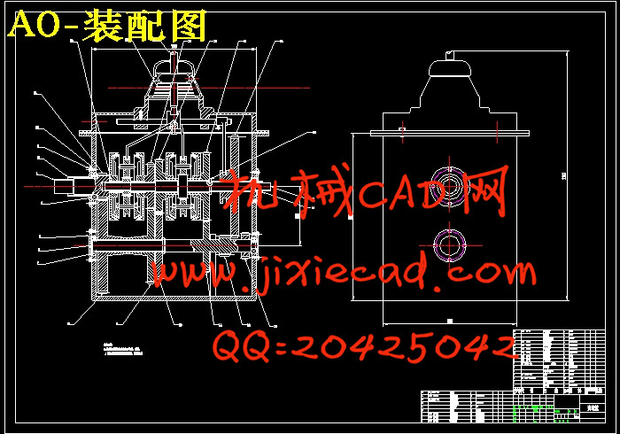
本文所设计的变速器中采用的是中间轴式变速器,其主要特点是可以设置发动机直接档获得高转速档位,较大的变速范围大可以满足不同的工况,不易损坏,维护方便,成本低。
关键词:变速器;齿轮;输入轴;结构
Abstract
The transmission is an important part of the car,it can change the engine's speed and torque in a wide range.Make the engine working in the best condition to meet the requirements of the car in different driving conditions.
The transmission's main design parameters are gear number,transmission ratio,center distance and the shape dimension of the transmission.This article is mainly based on the characteristics of low driving speed and high torque.After determining the main design parameters of the transmission, the main components of the transmission are designed. Such as the transmission structure scheme selection, each gear's design and check,each axis's design and check,choose the synchronizer,design of gearbox enclosure and so on.
In this paper,the intermediate shaft transmission is adopted in the transmission.Its main feature is that the engine can be set up directly gear to obtain high speed gear,large variable speed range can meet different working conditions,nonperishable,easy maintenance and low cost.
Key words: transmission;gear;input shaft;structure
目录
摘要 III
第一章 绪论 1
1.1变速器的功能 1
1.2变速器的分类 1
1.3研究意义 1
第二章 变速器结构方案选择 2
2.1变速器轴数选择 2
2.2档数的选择 2
2.3换挡结构方案选择 2
2.4倒档形式选择 3
2.5确定变速器传动方案 4
2.6设计参数 4
第三章 主要参数设计计算 5
3.1最大传动比 5
3.2最小传动比 5
3.3各档传动比 5
3.4中心距 6
3.5确定齿轮参数 6
3.5.1齿轮模数 6
3.5.2压力角 7
7
3.5.3螺旋角 及旋向 7
及旋向 7
3.5.4齿宽b 7
3.5.5变位系数 8
3.6各档齿轮齿数分配 8
3.6.1确定一档齿轮齿数 8
3.6.2确定二档齿轮齿数 9
3.6.3确定三档齿轮齿数 9
3.6.4确定四档齿轮齿数 10
3.6.5确定五档齿轮齿数 10
3.6.6确定倒档齿轮齿数 10
第四章 各档齿轮的校核 11
4.1齿轮接触疲劳强度校核 11
4.1.1 1、2号齿接触疲劳强度校核 11
4.1.2 3、4号齿接触疲劳强度校核 13
4.1.3 5、6号齿接触疲劳强度校核 14
4.1.4 7、8号齿接触疲劳强度校核 15
4.1.5 9、10号齿接触疲劳强度校核 17
4.1.6 倒档齿接触疲劳强度校核 18
4.2齿轮弯曲应力校核 19
4.2.1 1、2号齿轮弯曲应力校核 20
4.2.2 3、4号齿轮弯曲应力校核 22
4.2.3 5、6号齿轮弯曲应力校核 23
4.2.4 7、8号齿轮弯曲应力校核 25
4.2.5 9、10号齿轮弯曲应力校核 26
4.2.6 倒档齿轮弯曲应力校核 28
第五章 轴的设计计算 30
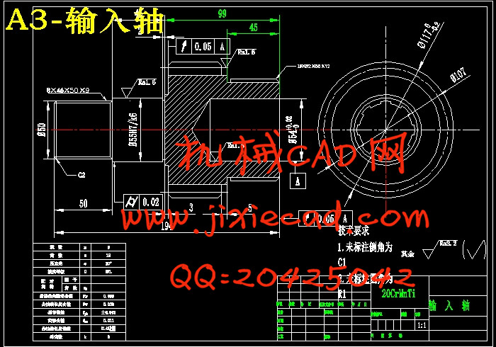
5.1输入轴的结构设计 30
5.2输入轴强度校核 30
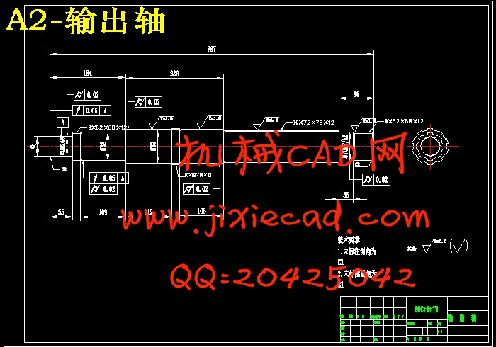
5.3输出轴的结构设计 31
5.3输出轴强度校核 33
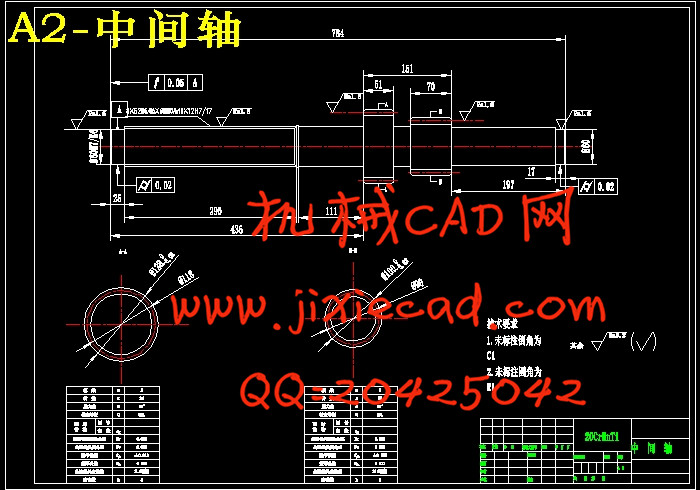
5.4中间轴的结构设计 34
5.5中间轴强度校核 34
参考文献 37
变速器是汽车的重要组成部分,它可以在较大范围内改变发动机的输出转速和转矩,使发动机在最佳的工作状态满足汽车在不同行驶状况下的工作要求。
对于变速器的设计,其主要的设计参数有档位数、各挡传动比、中心距和变速器的外形尺寸。本文主要根据大型车辆工作时行驶速度低,扭矩大的特点,在确定了变速器的主要设计参数后,对变速器主要组成部件进行了设计,如变速器结构方案选择、各挡齿轮的设计校核、各轴的设计校核、同步器选择、变速器箱体的设计等。
本文所设计的变速器中采用的是中间轴式变速器,其主要特点是可以设置发动机直接档获得高转速档位,较大的变速范围大可以满足不同的工况,不易损坏,维护方便,成本低。
关键词:变速器;齿轮;输入轴;结构
Abstract
The transmission is an important part of the car,it can change the engine's speed and torque in a wide range.Make the engine working in the best condition to meet the requirements of the car in different driving conditions.
The transmission's main design parameters are gear number,transmission ratio,center distance and the shape dimension of the transmission.This article is mainly based on the characteristics of low driving speed and high torque.After determining the main design parameters of the transmission, the main components of the transmission are designed. Such as the transmission structure scheme selection, each gear's design and check,each axis's design and check,choose the synchronizer,design of gearbox enclosure and so on.
In this paper,the intermediate shaft transmission is adopted in the transmission.Its main feature is that the engine can be set up directly gear to obtain high speed gear,large variable speed range can meet different working conditions,nonperishable,easy maintenance and low cost.
Key words: transmission;gear;input shaft;structure
目录
摘要 III
第一章 绪论 1
1.1变速器的功能 1
1.2变速器的分类 1
1.3研究意义 1
第二章 变速器结构方案选择 2
2.1变速器轴数选择 2
2.2档数的选择 2
2.3换挡结构方案选择 2
2.4倒档形式选择 3
2.5确定变速器传动方案 4
2.6设计参数 4
第三章 主要参数设计计算 5
3.1最大传动比 5
3.2最小传动比 5
3.3各档传动比 5
3.4中心距 6
3.5确定齿轮参数 6
3.5.1齿轮模数 6
3.5.2压力角
3.5.3螺旋角
3.5.4齿宽b 7
3.5.5变位系数 8
3.6各档齿轮齿数分配 8
3.6.1确定一档齿轮齿数 8
3.6.2确定二档齿轮齿数 9
3.6.3确定三档齿轮齿数 9
3.6.4确定四档齿轮齿数 10
3.6.5确定五档齿轮齿数 10
3.6.6确定倒档齿轮齿数 10
第四章 各档齿轮的校核 11
4.1齿轮接触疲劳强度校核 11
4.1.1 1、2号齿接触疲劳强度校核 11
4.1.2 3、4号齿接触疲劳强度校核 13
4.1.3 5、6号齿接触疲劳强度校核 14
4.1.4 7、8号齿接触疲劳强度校核 15
4.1.5 9、10号齿接触疲劳强度校核 17
4.1.6 倒档齿接触疲劳强度校核 18
4.2齿轮弯曲应力校核 19
4.2.1 1、2号齿轮弯曲应力校核 20
4.2.2 3、4号齿轮弯曲应力校核 22
4.2.3 5、6号齿轮弯曲应力校核 23
4.2.4 7、8号齿轮弯曲应力校核 25
4.2.5 9、10号齿轮弯曲应力校核 26
4.2.6 倒档齿轮弯曲应力校核 28
第五章 轴的设计计算 30
5.1输入轴的结构设计 30
5.2输入轴强度校核 30
5.3输出轴的结构设计 31
5.3输出轴强度校核 33
5.4中间轴的结构设计 34
5.5中间轴强度校核 34
参考文献 37