设计简介
摘 要
汽车在路面上行驶,由于受到不同路况的影响,不可避免的会出现颠簸、倾斜等情况,从而导致运输货物的倾洒、泄露、爆炸等危险。智能化自适应自稳移动平台可以消除载体运动和干扰力矩的影响,通过姿态传感器获取对平台变化的动态数据,计算倾斜程度,然后通过单片机整理数据,驱动直线电机运动,反复调整确保动态姿态符合标准。从而隔离外界对装置的干扰,使平台一直处于水平状态,确保货物的安全运输。稳定平台广泛的应用于各行各业中,其也成为当前国际上研究的重点课题。
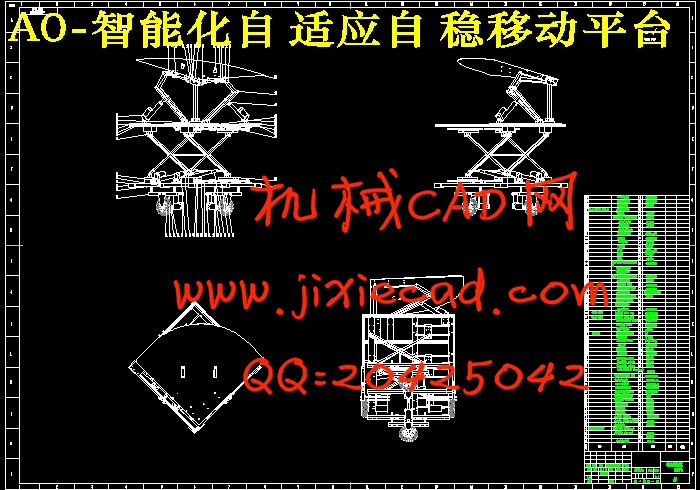
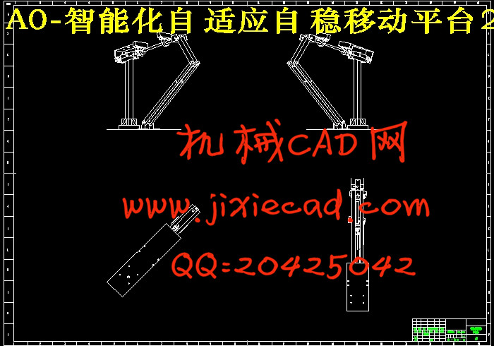
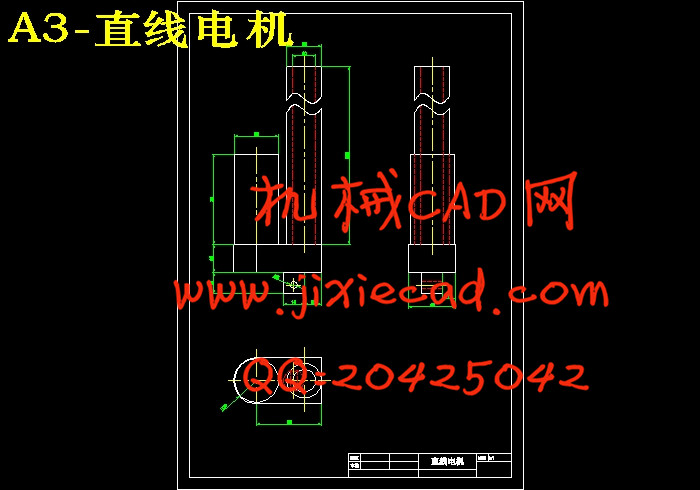
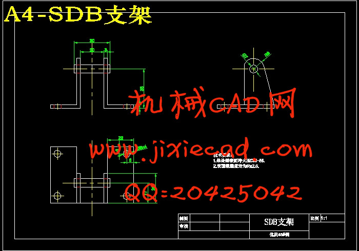
本文首先设计了一种新型的车载自稳平台,该自稳平台主要包括直线电机装置、四杆机构、剪叉机构、底盘机构等。其主要结构参数为:长800mm,宽800mm,高870mm,净重20Kg,最大起升后高度1.27m。该装置总体分为两部分:上部平台部分的功能是在遇到颠簸时可以通过调整自身的姿势变化而始终保持水平平稳状态,从而实现隔离运动物体扰动的功能。下部车体部分由剪叉升降机构及全向轮底盘组成,可通过智能遥控系统进行定位升降,其功能是使平台做任意方向的运动和原地360°无死角转动。
然后对稳定平台的自稳机构进行了运动分析和静力学分析,分析结果能够达到自动调节功能。
最后,利用solidworks软件对机构进行了仿真运动,用matlab进行数据分析。证明其可以完成既定的自稳、升降和移动要求。
通过该毕业设计可以实现智能化自适应自稳移动平台的各项既定功能。
关键词:自稳平台;直线电机;万向节;solidworks
ABSTRACT
Due to the impact of different roads conditions, there will be bumps or tilt during the car on the road inevitably, which results in the danger of goods to be transported dumping, leakage, explosion and other hazards. The intelligent adaptive self-stabilizing mobile platform can eliminate the influence of the carrier motion and the disturbance torquezit, obtain the dynamic data of the platform change through the attitude sensor, calculate the inclination degree, and then adjust the data through the single-chip microcomputer to drive the linear motor movement and adjust the dynamic attitude standard. Thus isolating the outside device interference, so that the platform has been in a horizontal state to ensure the safe transport of goods. Stable platform widely used in all walks of life, which has become the focus of the current international research topics.
First of all, this paper designs a new type of vehicle self-stabilizing platform, which includes linear motor device, four-bar mechanism,scissor mechanism and chassis mechanism. The main parameters are: length 800mm, width 800mm, height 870mm, net weight 20Kg, the maximum height after rise is 1.27m. The device is divided into two parts:the upper part is the platform part, which can be adjusted by changing their own posture when encountering in the bumps and always maintain a steady state of the level, so as to achieve the function of isolation movement object disturbance. the lower part is the body part,which composed of scissor lifting mechanism and omni-directional chassis. It can be lifted in any point by intelligent remote control system. Its function is to make the platform to do any direction’s movement and in situ 360 ° no dead angle rotation.
Secondly, the motion analysis and static analysis of the self-stabilizing mechanism of the stable platform are carried out,and the analysis result can achieve the function of automatic adjustment.
Finally, Solidworks software is used to simulate the movement of the organization and using Matlab for data analysis. To prove that it can complete the established requirements of self-stabilization, lifting and moving.
Through the graduation design can achieve the established function of intelligent adaptive self-stabilization mobile platform.
Key words: self-stabilizing platform;linear motor;universal joint;solidworks
汽车在路面上行驶,由于受到不同路况的影响,不可避免的会出现颠簸、倾斜等情况,从而导致运输货物的倾洒、泄露、爆炸等危险。智能化自适应自稳移动平台可以消除载体运动和干扰力矩的影响,通过姿态传感器获取对平台变化的动态数据,计算倾斜程度,然后通过单片机整理数据,驱动直线电机运动,反复调整确保动态姿态符合标准。从而隔离外界对装置的干扰,使平台一直处于水平状态,确保货物的安全运输。稳定平台广泛的应用于各行各业中,其也成为当前国际上研究的重点课题。
本文首先设计了一种新型的车载自稳平台,该自稳平台主要包括直线电机装置、四杆机构、剪叉机构、底盘机构等。其主要结构参数为:长800mm,宽800mm,高870mm,净重20Kg,最大起升后高度1.27m。该装置总体分为两部分:上部平台部分的功能是在遇到颠簸时可以通过调整自身的姿势变化而始终保持水平平稳状态,从而实现隔离运动物体扰动的功能。下部车体部分由剪叉升降机构及全向轮底盘组成,可通过智能遥控系统进行定位升降,其功能是使平台做任意方向的运动和原地360°无死角转动。
然后对稳定平台的自稳机构进行了运动分析和静力学分析,分析结果能够达到自动调节功能。
最后,利用solidworks软件对机构进行了仿真运动,用matlab进行数据分析。证明其可以完成既定的自稳、升降和移动要求。
通过该毕业设计可以实现智能化自适应自稳移动平台的各项既定功能。
关键词:自稳平台;直线电机;万向节;solidworks
ABSTRACT
Due to the impact of different roads conditions, there will be bumps or tilt during the car on the road inevitably, which results in the danger of goods to be transported dumping, leakage, explosion and other hazards. The intelligent adaptive self-stabilizing mobile platform can eliminate the influence of the carrier motion and the disturbance torquezit, obtain the dynamic data of the platform change through the attitude sensor, calculate the inclination degree, and then adjust the data through the single-chip microcomputer to drive the linear motor movement and adjust the dynamic attitude standard. Thus isolating the outside device interference, so that the platform has been in a horizontal state to ensure the safe transport of goods. Stable platform widely used in all walks of life, which has become the focus of the current international research topics.
First of all, this paper designs a new type of vehicle self-stabilizing platform, which includes linear motor device, four-bar mechanism,scissor mechanism and chassis mechanism. The main parameters are: length 800mm, width 800mm, height 870mm, net weight 20Kg, the maximum height after rise is 1.27m. The device is divided into two parts:the upper part is the platform part, which can be adjusted by changing their own posture when encountering in the bumps and always maintain a steady state of the level, so as to achieve the function of isolation movement object disturbance. the lower part is the body part,which composed of scissor lifting mechanism and omni-directional chassis. It can be lifted in any point by intelligent remote control system. Its function is to make the platform to do any direction’s movement and in situ 360 ° no dead angle rotation.
Secondly, the motion analysis and static analysis of the self-stabilizing mechanism of the stable platform are carried out,and the analysis result can achieve the function of automatic adjustment.
Finally, Solidworks software is used to simulate the movement of the organization and using Matlab for data analysis. To prove that it can complete the established requirements of self-stabilization, lifting and moving.
Through the graduation design can achieve the established function of intelligent adaptive self-stabilization mobile platform.
Key words: self-stabilizing platform;linear motor;universal joint;solidworks
目 录
摘 要 …………………………………………………………………………………Ⅰ
ABSTRACT …………………………………………………………………………………Ⅱ
1 绪论 ……………………………………………………………………………………1
1.1研究背景……………………………………………………………………………1
1.2选题的理论意义和应用价值………………………………………………………1
1.3平台的国内外发展趋势……………………………………………………………2
2 移动平台概述 …………………………………………………………………………3
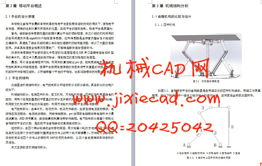
2.1平台的设计原理……………………………………………………………………3
2.2平台的结构…………………………………………………………………………3
3 机械结构分析 …………………………………………………………………………4
3.1自稳机构的比较与设………………………………………………………………4
3.1.1四杆机构 ………………………………………………………………………4
3.1.2万向节机构 ……………………………………………………………………5
3.1.3轴承与轴构成的局部自由度 ……………………………………………………6
3.2升降机构的比较与设计……………………………………………………………7
3.2.1丝杠式升降系统…………………………………………………………………7
3.2.2柱塞式升降系统…………………………………………………………………7
3.2.3机械传动的电动导轨式升降机构…………………………………………………8
3.2.4剪叉式升降机构…………………………………………………………………9
3.3 底盘机构的比较与设计 …………………………………………………………10
4 运动和力学分析 ………………………………………………………………………12
4.1 四杆机构的极限位置分析 ………………………………………………………12
4.2 四杆机构各杆的受力分析 ………………………………………………………13
4.3 四杆机构的压杆稳定校核 ………………………………………………………16
结论与展望 ………………………………………………………………………………20
参考文献 …………………………………………………………………………………21
致谢 ………………………………………………………………………………………22