设计简介
摘 要
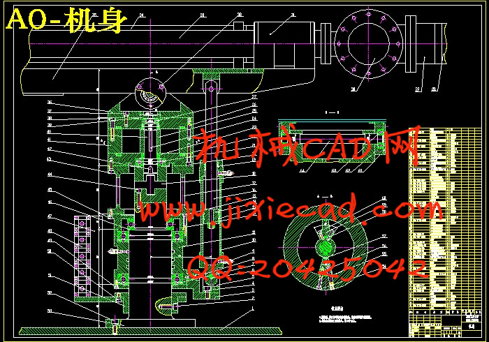
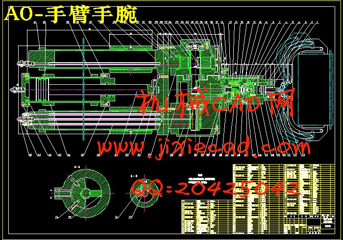
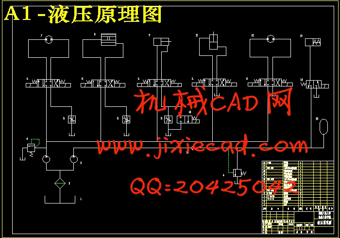
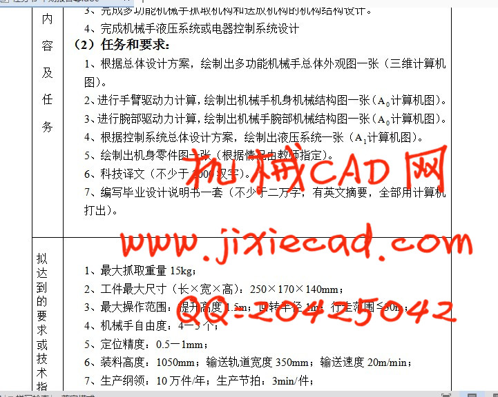
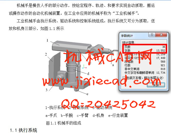
本次设计的多功能机械手用于R175型柴油机机体加工自动线上,主要由手爪、手腕、手臂、机身、机座等组成,具备上料、翻转和转位等多种功能,并按该自动线的统一生产节拍和生产纲领完成以上动作。本机械手机身采用机座式,自动线围绕机座布置,其坐标形式为球坐标式,具有立柱旋转、手臂伸缩、手臂俯仰、腕部转动和腕部摆动5个自由度。驱动方式为液压驱动,选用双联叶片泵,系统压力为2.5MPa,电机功率为5.5KW,共有整机回转油缸、手臂俯仰油缸、手臂伸缩油缸、手腕摆动油缸、手腕回转油缸、手爪夹紧油缸6个液压缸。送放机构的液压驱动系统是由液压基本回路组成,包括调压回路,缓冲回路,调速回路,换向回路.锁紧回路,保压回路。定位采用机械挡块定位,定位精度为0.5~1mm,采用行程控制系统实现点位控制。
关键词: 机械手,球坐标,液压,机械挡块 ,点位控制
ABSTRACT
The current design of multifunctional mechanical hand used for R175-type diesel organisms automatic processing line, mainly consist of claw, wrists, arms, body, base and so on. With moving the materials, turnover and transfer spaces, and many other functions, the automatic line with the unified production rhythms and production program completed more moves. With the automatic production line rhythms and the production of complete reunification of the above movements, automatic line is around the machine arrange, the coordinates of the ball coordinates of the form, with huge rotary, extendable arm, arm pitch, hitting and hitting back five moves freedom; Driven approach to hydraulic-driven, and the choice of double leaves pumps, the system pressure to 2.5MPa, 5.5KW electrical power for a total of whole sets of rotation tank, arm tilt cylinders, fuel tanks extendable arm, wrist swing tank, wrist rotation tank, claw clip tank six hydraulic oil tank; positioning a piece of machinery turned positioning, positioning accuracy for 0.5~1mm, using control systems to achieve their point spaces control.
Key words: Mechanical hand, the ball coordinates, hydraulic, mechanical turned pieces, control point spaces
目 录
第1章 概述............................................................1
1.1 执行系统.......................................................1
1.2 驱动系统.......................................................1
1.3 控制系统.......................................................2
第2章 方案设计及主要参数的确定....................................3
2.1 方案设计.......................................................3
2.2 主要参数的确定.................................................4
第3章 抓取机构的设计................................................5
3.1 抓取机构结构形式的确定.........................................5
3.2 夹紧力(握力)的确定............................................5
3.3 夹紧缸驱动力的计算.............................................7
3.4 夹钳式抓取机构的定位误差分析...................................8
3.5 夹紧液压缸主要尺寸的确定......................................10
3.5.1 液压缸内径D的计算......................................10
3.5.2 活塞杆直径d的计算......................................11
3.5.3 液压缸壁厚δ的计算......................................12
3.5.4 液压缸外径D0及长度l的计算..............................12
3.5.5 液压缸行程S的确定......................................12
第4章 送放机构的设计...............................................13
4.1概述............................................................13
4.2液压系统主要参数的确定..........................................14
4.2.1 液压缸工作载荷的确定....................................15
4.2.2 液压缸推力的确定........................................15
4.2.3 液压缸流量的计算........................................15
4.2.4 液压缸基本尺寸的确定....................................15
4.3机械手的腕部设计................................................16
4.3.1 腕部结构形式的确定......................................16
4.3.2 腕部回转缸驱动力矩的计算................................17
4.3.3 腕部回转液压缸尺寸的确定................................21
4.3.4 腕部摆动缸驱动力矩的计算................................22
4.3.5 腕部摆动液压缸尺寸的确定................................24
4.4机械手的手臂和机身的设计........................................25
4.4.1 手臂和机身结构形式的确定................................25
4.4.2 手臂驱动力的计算........................................27
4.5液压系统元件的选择..............................................31
4.6液压系统回路的分析..............................................31
4.6.1 调压回路................................................31
4.6.2 缓冲回路................................................32
4.6.3 调速回路................................................32
4.6.4 换向回路................................................33
4.6.5 锁紧回路................................................33
4.6.6 保压回路................................................33
第5章 控制系统的设计...............................................34
参考文献..............................................................35
致谢 ..................................................................36