设计简介
摘要
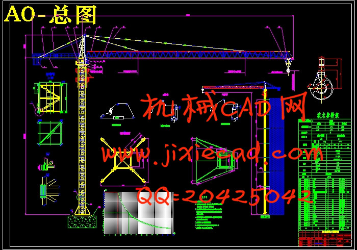
QTZ125型塔式起重机布置合理,外形美观,使用方便,维修简单,工作平稳,就位快捷方便、高效。该塔机为上回转,水平臂架,小车变幅,液压自升式多用途塔机,起重力矩为1250KN²m,最大起重量为10T,独立架设最大起升高度可达200m,最大变幅为63m。
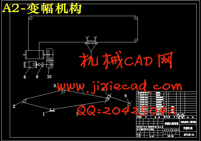
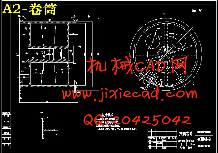
变幅机构是为了满足物料装卸工作位置要求,充分利用自身的起吊能力(幅度减少能提高起重量),实现改变幅度的工作机构,并用来扩大塔式起重机的工作范围,提高生产率。
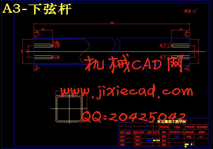
QTZ125塔式起重机是通过移动牵引起重小车实现变幅的。工作时吊臂安装在水平位置,小车由变幅牵引机构驱动,沿着吊臂轨道(弦杆)移动。小车变幅的优点是:变幅时物料做水平移动,安装就位方便;速度快、功率省;幅度有效利用率大。其缺点为:吊臂承受较大的弯距,结构笨重,用钢量大。绳索牵引式变幅机构的小车依靠钢丝绳牵引沿吊臂轨道运行,其驱动力不受附着力的限制,故能在略呈倾斜的轨道上行走,又由于驱动装置在小车外部,从而使小车自重大为减少,所以适用于大幅度起重量较大的起重机。在塔式起重机中大都采用绳索牵引式变幅机构,这样既可以减轻吊臂载荷,又可以使工作可靠,而且因为驱动装置放在吊臂根部,平衡重也可以减少。
关键词:QTZ125塔机、变幅机构、绳牵引小车式
ABSTRACT
QTZ125 tower crane has reasonable layout, beautiful appearance, it is convenient to use, it is simple to repair, it works stable convenient and efficient. The rotary mode is turning on,ir has horizontal jib, trolley, hydraulic jack-up multi-purpose cranes, its lifting moment is 1250KN ² m and the maximum lifting weight is 10T the maximum lifting height and amplitude is 200m and 63m.
Luffing mechanism make full use of its lifting capacity of (reduction can improve the weight) to meet the requirement of the material handling work location to change the working mechanism of amplitude and to expand the scope of tower crane work, improve productivity.
QTZ125 tower crane changes amplitude through a mobile traction lifting trolley. When the crane works the jib is installed in a horizontal position, the car alongs the crane rail (chord) move which drived by amplitude traction mechanism.The advantages are: when the trolley works the material move horizontally, it is convenient to install; it has fast speed, it saves power and the effective utilization rate is great. Its shortcomings are: the jib beers a big bending moment, heavy structure and a large quantity of steel. Rope traction luffing car moves along the boom in orbit rely on wire rope traction, its driving force is not affected by adhesion, it can be walking in slightly inclined orbit and because the driver in the car outside, so that the weight of the car is reduced greatly so it is suitable for large amplitude heavy crane. Most of the tower use crane rope traction luffing mechanism which not only can reduce the crane load but also can make reliable work and because the drive device on the jib root the balance weight can also reduced.
Keywords: QTZ125 tower crane, luffing mechanism, rope trolley type
目录
第一章 前言··················································································1
1.1塔式起重机概述············································································1
1.2塔式起重机的发展趋势····································································3
第二章 总体设计············································································4
2.1 概述························································································4
2.2 总体设计方案的确定······································································5
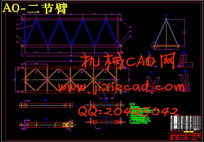
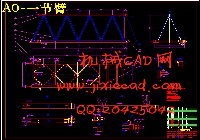
2.2.1金属结构·················································································5
2.2.2工作机构················································································25
2.3 总体设计原则············································································29
2.3.1 整机工作级别··········································································32
2.3.2 机构工作级别··········································································32
2.3.3 主要技术性能参数····································································32
2.4平衡臂与平衡重的计算···································································33
2.5起重特性曲线·············································································35
2.6塔机风力计算·············································································37
2.6.1工作工况Ⅰ············································································38
2.6.2工作工况Ⅱ·············································································42
2.6.3工作工况Ⅲ·············································································44
2.6.4非工作工况Ⅳ···········································································46
2.7整机的抗倾翻稳定性·····································································48
2.7.1工作工况Ⅰ·············································································49
2.7.2工作工况Ⅱ·············································································50
2.7.3非工作工况Ⅲ···········································································51
2.7.4工作工况Ⅳ·············································································51
第三章 塔身的设计计算·································································52
3.1塔身的总体模型···········································································52
3.2 塔身的受力分析及验算··································································53
3.2.1.塔身的受力分析·······································································53
3.2.2 塔身内力计算及组合··································································56
3.2.3 塔身整体稳定性和强度验算··························································59
第四章 变幅机构的设计和计算························································71
4.1变幅机构的形式··········································································71
4.2 确定卷筒尺寸············································································71
4.2.1 卷筒名义直径··········································································71
4.2.2 多层绕卷筒相关参数计算····························································72
4.3选择电动机、减速器、制动器、联轴器····················································72
4.3.1选择电动机·············································································72
4.3.2 选择减速器············································································73
4.3.3 变幅机构制动器的选择·······························································74
4.3.4变幅机构联轴器的选择································································75
4.4. 验算变幅速度···········································································77
4.5验算起、制动时间验算····································································77
4.6电动机发热校验···········································································79
4.7 校验卷筒强度············································································80
第五章 变幅小车的设计·······························································81
5.1 变幅小车的形式··········································································81
5.2 变幅小车的设计··········································································82
5.2.1 绳索牵引式小车构造及其驱动方式················································82
5.2.2运行小车牵引力计算···································································83
5.2.3 牵引绳最大张力·······································································86
5.2.4 选择牵引绳············································································87
5.2.5 牵引卷筒计算··········································································87
第六章 设计小结····································································90
致谢····························································································91
参考书目·······················································································93
QTZ125型塔式起重机布置合理,外形美观,使用方便,维修简单,工作平稳,就位快捷方便、高效。该塔机为上回转,水平臂架,小车变幅,液压自升式多用途塔机,起重力矩为1250KN²m,最大起重量为10T,独立架设最大起升高度可达200m,最大变幅为63m。
变幅机构是为了满足物料装卸工作位置要求,充分利用自身的起吊能力(幅度减少能提高起重量),实现改变幅度的工作机构,并用来扩大塔式起重机的工作范围,提高生产率。
QTZ125塔式起重机是通过移动牵引起重小车实现变幅的。工作时吊臂安装在水平位置,小车由变幅牵引机构驱动,沿着吊臂轨道(弦杆)移动。小车变幅的优点是:变幅时物料做水平移动,安装就位方便;速度快、功率省;幅度有效利用率大。其缺点为:吊臂承受较大的弯距,结构笨重,用钢量大。绳索牵引式变幅机构的小车依靠钢丝绳牵引沿吊臂轨道运行,其驱动力不受附着力的限制,故能在略呈倾斜的轨道上行走,又由于驱动装置在小车外部,从而使小车自重大为减少,所以适用于大幅度起重量较大的起重机。在塔式起重机中大都采用绳索牵引式变幅机构,这样既可以减轻吊臂载荷,又可以使工作可靠,而且因为驱动装置放在吊臂根部,平衡重也可以减少。
关键词:QTZ125塔机、变幅机构、绳牵引小车式
ABSTRACT
QTZ125 tower crane has reasonable layout, beautiful appearance, it is convenient to use, it is simple to repair, it works stable convenient and efficient. The rotary mode is turning on,ir has horizontal jib, trolley, hydraulic jack-up multi-purpose cranes, its lifting moment is 1250KN ² m and the maximum lifting weight is 10T the maximum lifting height and amplitude is 200m and 63m.
Luffing mechanism make full use of its lifting capacity of (reduction can improve the weight) to meet the requirement of the material handling work location to change the working mechanism of amplitude and to expand the scope of tower crane work, improve productivity.
QTZ125 tower crane changes amplitude through a mobile traction lifting trolley. When the crane works the jib is installed in a horizontal position, the car alongs the crane rail (chord) move which drived by amplitude traction mechanism.The advantages are: when the trolley works the material move horizontally, it is convenient to install; it has fast speed, it saves power and the effective utilization rate is great. Its shortcomings are: the jib beers a big bending moment, heavy structure and a large quantity of steel. Rope traction luffing car moves along the boom in orbit rely on wire rope traction, its driving force is not affected by adhesion, it can be walking in slightly inclined orbit and because the driver in the car outside, so that the weight of the car is reduced greatly so it is suitable for large amplitude heavy crane. Most of the tower use crane rope traction luffing mechanism which not only can reduce the crane load but also can make reliable work and because the drive device on the jib root the balance weight can also reduced.
Keywords: QTZ125 tower crane, luffing mechanism, rope trolley type
目录
第一章 前言··················································································1
1.1塔式起重机概述············································································1
1.2塔式起重机的发展趋势····································································3
第二章 总体设计············································································4
2.1 概述························································································4
2.2 总体设计方案的确定······································································5
2.2.1金属结构·················································································5
2.2.2工作机构················································································25
2.3 总体设计原则············································································29
2.3.1 整机工作级别··········································································32
2.3.2 机构工作级别··········································································32
2.3.3 主要技术性能参数····································································32
2.4平衡臂与平衡重的计算···································································33
2.5起重特性曲线·············································································35
2.6塔机风力计算·············································································37
2.6.1工作工况Ⅰ············································································38
2.6.2工作工况Ⅱ·············································································42
2.6.3工作工况Ⅲ·············································································44
2.6.4非工作工况Ⅳ···········································································46
2.7整机的抗倾翻稳定性·····································································48
2.7.1工作工况Ⅰ·············································································49
2.7.2工作工况Ⅱ·············································································50
2.7.3非工作工况Ⅲ···········································································51
2.7.4工作工况Ⅳ·············································································51
第三章 塔身的设计计算·································································52
3.1塔身的总体模型···········································································52
3.2 塔身的受力分析及验算··································································53
3.2.1.塔身的受力分析·······································································53
3.2.2 塔身内力计算及组合··································································56
3.2.3 塔身整体稳定性和强度验算··························································59
第四章 变幅机构的设计和计算························································71
4.1变幅机构的形式··········································································71
4.2 确定卷筒尺寸············································································71
4.2.1 卷筒名义直径··········································································71
4.2.2 多层绕卷筒相关参数计算····························································72
4.3选择电动机、减速器、制动器、联轴器····················································72
4.3.1选择电动机·············································································72
4.3.2 选择减速器············································································73
4.3.3 变幅机构制动器的选择·······························································74
4.3.4变幅机构联轴器的选择································································75
4.4. 验算变幅速度···········································································77
4.5验算起、制动时间验算····································································77
4.6电动机发热校验···········································································79
4.7 校验卷筒强度············································································80
第五章 变幅小车的设计·······························································81
5.1 变幅小车的形式··········································································81
5.2 变幅小车的设计··········································································82
5.2.1 绳索牵引式小车构造及其驱动方式················································82
5.2.2运行小车牵引力计算···································································83
5.2.3 牵引绳最大张力·······································································86
5.2.4 选择牵引绳············································································87
5.2.5 牵引卷筒计算··········································································87
第六章 设计小结····································································90
致谢····························································································91
参考书目·······················································································93