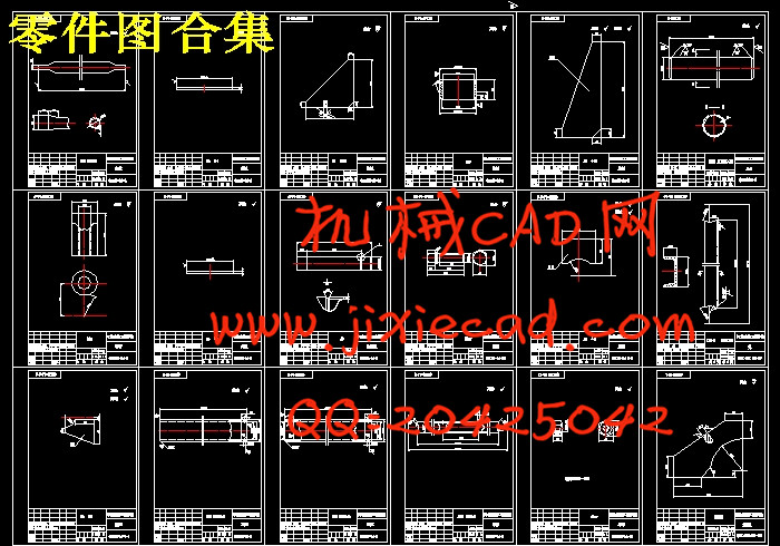
设计简介
摘要
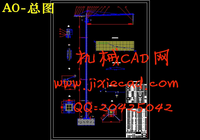
本次设计在参照同类塔式起重机基础上,对QTZ40型塔式起重机进行总体设计及塔身分析设计。在塔身设计工程中,采用了有限元法对其进行分析计算,采用了ANSYS10.0软件进行分析。
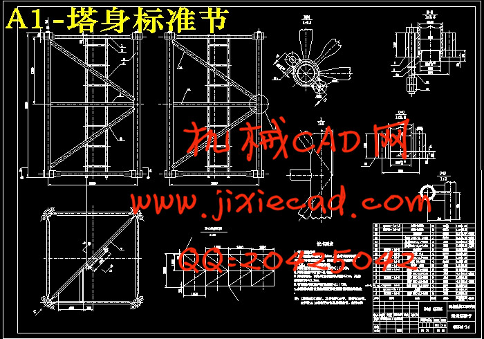
按照整机主要性能参数,确定各机构类型及钢结构型式,主要确定了塔身的结构参数,并按照风载荷平行于起重臂方向,风载荷与起重臂方向呈45度角时两种工况分析。通过对塔身作适当的简化,应用ANSYS10.0软件建立塔身的有限元模型,施加各工况载荷,进行求解,进而可得各工况下各节点受力情况及各单元所受轴向力、轴向应力大小及各工况下塔身的变形挠度大小,并能演示塔身加载过程的动画,清晰的展现了各工况下塔身的受力性能。
本次设计分析通过修改模型参数共准备了三种不同方案,进而对不同模型方案进行分析比较。由比较不同模型在相同工况下的受力状况及刚度状况,综合分析强度和刚度条件,可得出受力最为合理的一组模型参数,通过对此组参数下模型进行强度及刚度校核,进而获得塔身的最终参数结果。
关键词:QTZ40型塔式起重机 塔身 有限元分析 ANSYS10.0
Abstract
Based on the design of the similar tower crane, this design is composed of the system design and the tower body design of the QTZ40 tower crane. In the tower body design progress, it has carried Finite Element Method on the analysis computation, and used ANSYS10.0 software.
According to the entire machine main performance parameters, various organizations type and the steel structure pattern have been determined. And then, the parameter analysis is carried on two different operating modes which are composed of the direction of the wind load is parallel to the lazy arm and the direction of the wind load is at a 45 degrees angle with the lazy arm. Through the reasonable simplification of the tower body, the tower body finite element model is established by applying ANSYS12.0 software, and then it’s exerted various operating modes loads, and carried on the solution. Then ANSYS10.0 software can calculate various nodes stress situation, the axial stress various units receive, and the tower body distortion size under various operating modes. Also it can demonstrate the animation in the loads-carrying process on the tower body, which has clearly displayed the stress performance of the tower body under various operating modes.
Through the revision of the model parameters, three different schemes have been prepared for the analysis comparison, which is carried on the different models. Because the stress condition and stiffness condition of different model are compared under the same operating mode, and a comprehensive analysis of the intensity and the stiffness condition is carried on, a most reasonable model parameter can be obtained. Through the intensity and the stiffness examination regarding this model, then the final parameter result of the tower body can be obtained.
Key words: QTZ40 tower crane Tower body Finite element analysis ANSYS10.0
目录
第1章 前言······················································1
1.1 塔式起重机概述··············································1
1.2 塔式起重机的发展情况········································1
1.3 塔式起重机的发展趋势·······································3
第2章 总体设计··················································5
2.1 概述······················································· 5
2.2 确定总体设计方案············································5
2.2.1 金属结构···············································5
2.2.2 工作机构···············································22
2.2.3 安全保护装置···········································29
2.3 总体设计设计总则···········································32
2.3.1 整机工作级别 ··········································32
2.3.2 机构工作级别···········································32
2.3.3主要技术性能参数······································· 33
2.4 平衡重的计算···············································33
2.5 起重特性曲线···············································35
2.6 塔机风力计算·············································· 36
2.6.1 工作工况Ⅰ············································37
2.6.2 工作工况Ⅱ············································41
2.6.3 非工作工况Ⅲ···········································43
2.7整机的抗倾翻稳定性·········································45
2.7.1工作工况Ⅰ············································46
2.7.2工作工况Ⅱ············································47
2.7.3非工作工况Ⅲ··········································49
2.7.4工作工况Ⅳ············································50
2.8固定基础稳定性计算·········································51
第3章 塔身的有限元分析设计···································53
3.1 塔身模型简化···············································53
3.2 有限元分析计算·············································54
3.2.1 方案一···············································54
3.2.2 方案二··············································79
3.2.3 方案三··············································98
第4章 塔身的受力分析计算····································121
4.1 稳定性校核················································121
4.2 塔身的刚度检算············································122
4.3 塔身的强度校核············································124
4.4 链接套焊缝强度的计算······································125
4.5 塔身腹杆的计算············································126
4.6 高强度螺栓强度的计算······································127
第5章 设计小结···········································129
致谢·····························································130
主要参考文献····················································131


