设计简介
摘要
在现代化生产加工领域中,对于大件材料、零件的搬运,机床加工中的进上,产品整体的装配等实现自动化是非常有必要的。更何况搬运是一项十分繁重、非常劳累的工作,为了提高生产的效率、减少重复的体力劳动、减少工人的数量,降低劳动力的投入,保证生产安全的进行,所以采用自动化输送系统是非常有效的方式,也是非常科学的方法。自动生产线的灵活性较高,可以实现对不同规格和标准的产品的生产而且其生产机械和生产装置能够自动的完成产品的各道生产加工过程,并且这种加工能够保证产品的质量。自动化输送设备出现以来,大幅降低了生产成本、提高了生产效率,并且易于控制,因此在现代化工厂中被广泛应用。
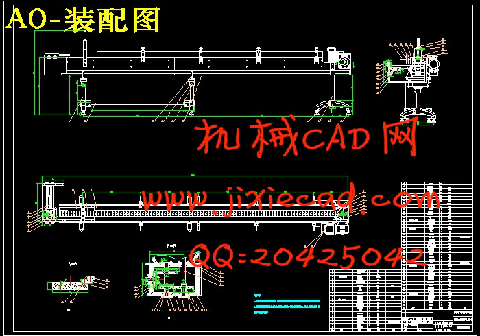
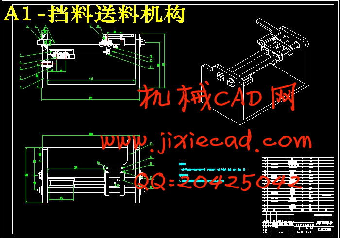
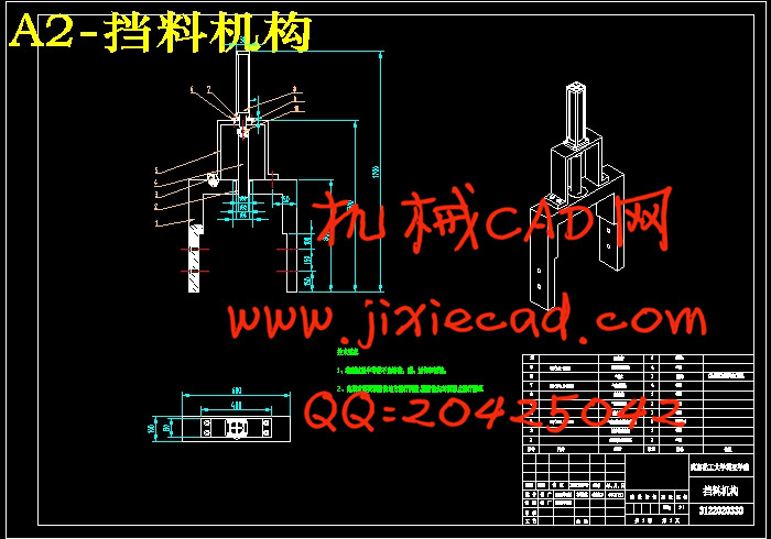
本设计的履带式盘类形状上料仓是自动上料设备中除了机械上料装(机械手)之外的,用来存储已经依次排列的工件,然后把工件依次送至上料装置上料位置的机械装置。思路来源于沈阳第一机床厂的轴承外环全自动加工设备,以轴承外环加工的上料工艺为基础,详细了解自动化生产线中履带式传送带的基本情况,并对生产线中盘类形状零件的上料进行了阐述;而后对自动化生产线中的上料仓的组成和功能进行了详细的说明,使读者能够更好地理解所设计的机构;本设计中为了确保履带传送的传输效率、输出转矩及功率的问题,对传动方案进行了详细的选型设计,通过直线段阻力、曲线段阻力、挡板阻力和工件阻力确定了传送带阻力,通过计算得料仓所需功率从而对电动机进行了选型,确定了电动机的输出转矩、功率等;本文还通过计算气缸的缸径、行程的计算、气缸的安装形式、缓冲装置对挡料机构的气缸进行了选型,确定乐气缸行程传感器的尺寸与型号,通过计算得出了挡料机构料道的总长度和总宽度,确定隔料器的型号及其驱动方式,确定定位装置导轨轴的材料及最小直径。
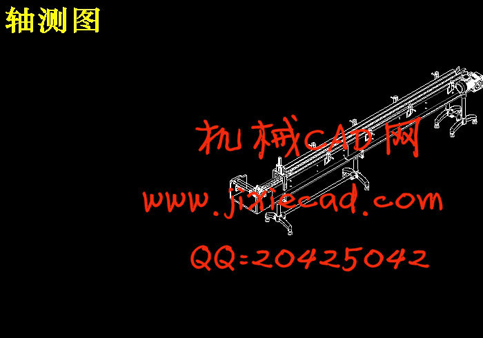
最后,本文还基于solidworks软件对履带式盘类形状上料仓进行了建模及装配,通过零件装配而成的三维立体图更加直观的显示了本次设计的装置。
关键词:履带式;上料仓;电机;solidworks;
Abstract在现代化生产加工领域中,对于大件材料、零件的搬运,机床加工中的进上,产品整体的装配等实现自动化是非常有必要的。更何况搬运是一项十分繁重、非常劳累的工作,为了提高生产的效率、减少重复的体力劳动、减少工人的数量,降低劳动力的投入,保证生产安全的进行,所以采用自动化输送系统是非常有效的方式,也是非常科学的方法。自动生产线的灵活性较高,可以实现对不同规格和标准的产品的生产而且其生产机械和生产装置能够自动的完成产品的各道生产加工过程,并且这种加工能够保证产品的质量。自动化输送设备出现以来,大幅降低了生产成本、提高了生产效率,并且易于控制,因此在现代化工厂中被广泛应用。
本设计的履带式盘类形状上料仓是自动上料设备中除了机械上料装(机械手)之外的,用来存储已经依次排列的工件,然后把工件依次送至上料装置上料位置的机械装置。思路来源于沈阳第一机床厂的轴承外环全自动加工设备,以轴承外环加工的上料工艺为基础,详细了解自动化生产线中履带式传送带的基本情况,并对生产线中盘类形状零件的上料进行了阐述;而后对自动化生产线中的上料仓的组成和功能进行了详细的说明,使读者能够更好地理解所设计的机构;本设计中为了确保履带传送的传输效率、输出转矩及功率的问题,对传动方案进行了详细的选型设计,通过直线段阻力、曲线段阻力、挡板阻力和工件阻力确定了传送带阻力,通过计算得料仓所需功率从而对电动机进行了选型,确定了电动机的输出转矩、功率等;本文还通过计算气缸的缸径、行程的计算、气缸的安装形式、缓冲装置对挡料机构的气缸进行了选型,确定乐气缸行程传感器的尺寸与型号,通过计算得出了挡料机构料道的总长度和总宽度,确定隔料器的型号及其驱动方式,确定定位装置导轨轴的材料及最小直径。
最后,本文还基于solidworks软件对履带式盘类形状上料仓进行了建模及装配,通过零件装配而成的三维立体图更加直观的显示了本次设计的装置。
关键词:履带式;上料仓;电机;solidworks;
In the field of modern production and processing, Achieving automation is very necessary for handling of bulk materials and parts, processing of machine tool, the assemblage of whole products. Besides transferring of cargo is a very heavy and tiring work, in order to improve production efficiency and reduce repetitive manual labor, reduce worker number, reduce labor input to ensure the safety of production, so the automatic conveying system is very effective way, is also very scientific method. Automatic production line can realize the production of different specifications and standards, the production of machinery and production device automatically finishing product of the production process because of it’s higher flexibility. And this process can ensure the quality of the products. Since the advent of the automated transportation equipment, the production cost has been greatly reduced, the production efficiency has been improved and controlled easily, Therefore automation equipment has been widely used in the modern chemical plant.
The design of the crawler plate shape of silo is used to store arranged the workpiece besides mechanical loading (manipulator) in automatic feeding equipment .Then the mechanical device of the workpiece are sent first feeding feeding position. My train of thought is from the first machine tool plant in Shenyang bearing outer ring fully automatic processing equipment, it is based on the processing of the outer ring of the bearing,it not only describes the basic situation automatic production line of a crawler type conveying belt, and describes the production line in the disk shape parts material; Then, readers can better understand the mechanism through a detailed description on the automatic production line of the silo composition and function,; In order to ensure the transmission efficiency of the crawler, output torque and power, This design carries on the detailed design to the transmission scheme,The conveyor belt resistance is determined by the straight line segment resistance, the resistance of the curve segment, the resistance of the baffle and the resistance of the workpiece; By calculating the power required to get bin for the selection of the motor, determines the motor output torque, power etc. This article also calculated the calculation of the bore and stroke of the cylinder, the installation of the cylinder form, buffer device for keep-off mechanism type selection, the cylinder of determine the size and type of the cylinder stroke sensor block body material obtained by calculation way of the total length and total width, make sure every feeder model and its driving mode, the guide shaft positioning device materials and minimum diameter.
At the end of this paper, This paper is based on the SolidWorks software for the crawler plate shape of silo modeling and assembly, The three-dimensional map is formed by the assembly of parts more intuitive display device of this design.
Key words:caterpillar;Bin;the motor;solidworks;
目 录
第一章前言 1
1.1 履带式盘类形状上料仓概述 1
1.1.1 自动化生产线的概述 1
1.1.2 自动化生产线中输送设备的概述 1
1.1.3 自动生产线中盘类形状上料仓的概述 3
1.2 履带式盘类形状上料仓的组成及作用 3
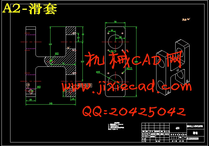
1.2.1 履带式盘类形状上料仓的组成 3
1.2.2 履带式盘类形状上料仓的作用 5
第二章履带式盘类形状上料仓的传动系统设计 6
2.1 履带式盘类形状上料仓的关键技术参数要求 6
2.2 履带式盘类形状上料仓的传动方案设计 7
2.3 履带式盘类形状上料仓的驱动电机选择 9
2.3.1 履带式盘类形状上料仓传送带阻力FW 9
2.3.2 履带式盘类形状上料仓所需功率Pw 11
2.3.3 电机所需的输出功率P0 12
2.3.4 电机所需的额定功率Pm 13
2.4 履带式盘类形状上料仓的气缸选择 15
第三章履带式盘类形状上料仓的主体部分结构设计 18
3.1 履带式盘类形状上料仓的传感器的选用 18
3.1.1 所选用的传感器的工作原理 18
3.1.2 扩散反射式光电开关 19
3.1.3 气缸行程传感器的选择 19
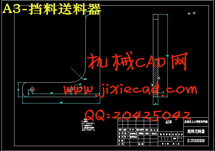
3.2 履带式盘类形状上料仓的挡料结构设计 20
3.2.1 料仓结构的常见形式 20
3.2.2 挡料机构料道的设计 21
3.2.3 挡料机构的隔料器设计 23
3.3 履带式盘类形状上料仓的定位结构设计 26
3.3.1 定位结构分析及工作原理 26
3.3.2 导轨轴的设计 27
第四章基于Solidworks进行履带式盘类形状上料仓建模装配 30
4.1 Solidworks软件建模与装配概述 30
4.1.1 Solidworks软件介绍 30
4.1.2 建模及装配概述 30
4.2 Solidworks零件设计 30
4.3 运用Solidworks软件进行零件装配 34
第五章结论 38
参考文献 39
致谢 40