设计简介
坐标形式:球坐标
| 坐标系 | 抓重 | 自由度 | 伸缩X | 升降Z |
| 球坐标 | 200N | 4 | 350mm,<200mm/s |
| 横移Y | 回转φ | 俯仰θ |
| 0°~210°,<90°/s |
0°~45°,<90°/s |
| 回转ω | 手指夹持范围 |
| 0°~180°,<90°/s | 棒料,直径φ40~φ60,长度450~1200mm |
| 定位方式 | 驱动方式 | 定位精度 | 控制方式 |
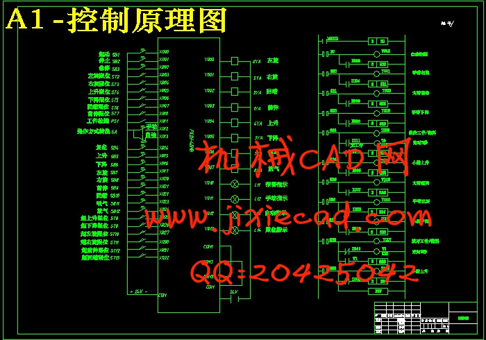
| 电位器(或接近开关等)设定,点位控制 | 液压(中、低压系统) | ±3mm | PLC控制 |
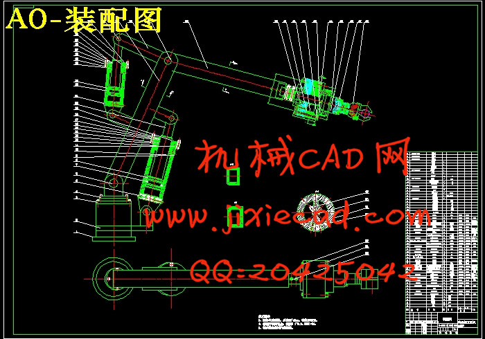
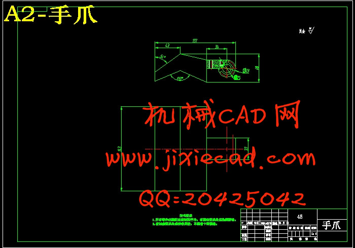
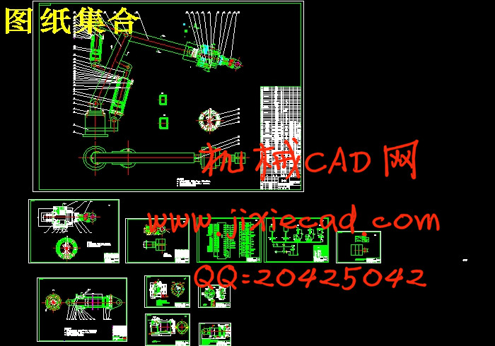
本次设计所确定的机械手的整体结构为球坐标式机械手,手臂动作为摆动或者转动,手爪的动作为伸缩和松夹。由于此机械手的动作要求放置不同的工件,所以实现上下料过程也要求手腕能旋转动作。
本文的机械手用于棒料,直径φ40~φ60,长度450~1200mm,介绍它的组成和分类、自由度和座标型式、液压技术的特点、PLC控制的特点及国内外的发展状况,对机械手进行总体方案设计,确定机械手的座标型式和自由度,确定机械手的技术参数,设计机械手的手臂结构,设计出机械手的液压系统,绘制机械手液压系统工作原理图。利用可编程序控制器对机械手进行控制,选取合适的PLC型号,根据机械手的工作流程制定可编程序控制器的控制方案,画出机械手的工作时的顺序功能图和梯形图,并编制可编程序控制器的控制程序。
关键词:机械手, 球坐标工业机械手,抓取,棒料;液压;PLC
Abstract
Industrial machinery hand (hereinafter referred to as the manipulator) is a new technology of modern automatic control in the field, as the edge disciplines multidisciplinary integration, it is one of the fastest growing areas of high technology, and has become an important part of modern machinery manufacturing in the production system. The so-called industrial manipulator is a complete object automatically according to the given procedures or requirements (such as materials, parts, components or tools) mechanical device to transmit or operation, it can partly replace the manual labor. The manipulator of higher level type, can simulate human arm movement, complex operation.The overall structure of the design of manipulator and the spherical coordinate manipulator, arm movements as swing or rotation, the gripper action for expansion and loose clamp. Because the mechanical hand movements placed different workpieces, so the implementation process on the wrist rotation is required.
In this paper, the mechanical hand for bar, diameter φ 40~ φ 60, length 450~1200mm, introduces its composition and classification, degree of freedom and coordinate type, hydraulic technology characteristics, PLC control characteristics and development at home and abroad, for the overall design of manipulator, to determine the coordinates of the manipulator types and degrees of freedom, to determine the technical parameters of the manipulator, manipulator arm structure design, hydraulic system design of mechanical hand, draw the working principle of the hydraulic system of manipulator diagram. The control of the manipulator programmable controller, select the appropriate PLC model, according to the workflow manipulator developed PLC control program, draw the mechanical hand work of the sequential function chart and the ladder diagram, and control program of programmable controlle
Keywords: manipulator, spherical coordinate industrial manipulator, grasping, bar; hydraulic; PLC
目 录
摘 要 IIAbstract III
目 录 IV
1 绪 论 1
1.1选题背景 1
1.2 机械手发展现状和趋势 2
1.3 机械手的系统工作原理及组成 2
1.3 球坐标工业机械手的组成 2
2 球坐标工业机械手设计要求与方案 3
2.1 球坐标工业机械手技术参数 3
2.2总体方案分析 3
2.3 动作原理 4
2.4 工业机械手的传动方案设计 4
2.5球坐标工业机械手驱动方式的选择 5
3 球坐标工业机械手各主要组成部分设计 7
3.1手部结构 7
3.1.1手部结构种类 7
3.1.2 夹持器设计计算 8
3.1.3手部校核 9
3.2 升降方向设计计算 9
3.2.1 初步确系统压力 10
3.2.2 升降油缸计算 10
3.3油缸主要部位的计算校核 14
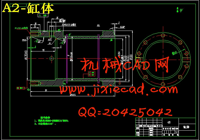
3.3.1缸筒壁厚的计算 14
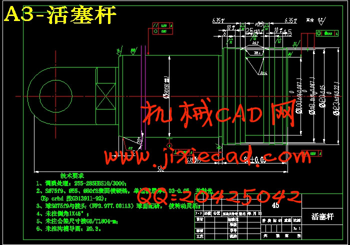
3.3.2 活塞杆强度和液压缸稳定性计算 15
3.3.3缸筒壁厚的验算 17
3.3.4 缸筒的加工要求 18
3.3.5法兰设计 19
3.3.6 (缸筒端部)法兰连接螺栓的强度计算 19
3.4 活塞的设计 21
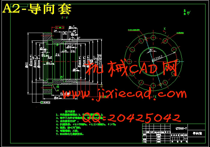
3.5 导向套的设计与计算 22
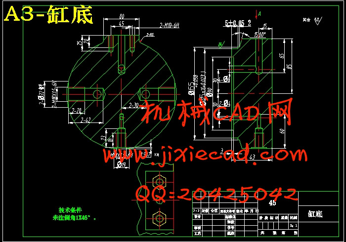
3.6 端盖和缸底的设计与计算 24
3.7 缸体长度的确定 25
3.8 缓冲装置的设计 25
3.9 排气装置 26
3.10 密封件的选用 28
3.11 防尘圈 29
3.12 液压缸的安装连接结构 30
3.13 水平方向设计计算 33
3.13.1 水平方向计算 33
3.13.2 油缸的选型 33
3.14 底座回转机构设计计算 33
3.14.1 回转部位负载计算校核 34
3.14.2 油马达的选型 35
3.15机身结构的设计校核 37
3.15.1 油马达的选择 37
3.15.2螺柱的设计与校核 37
3.15.3机座的机械结构 38
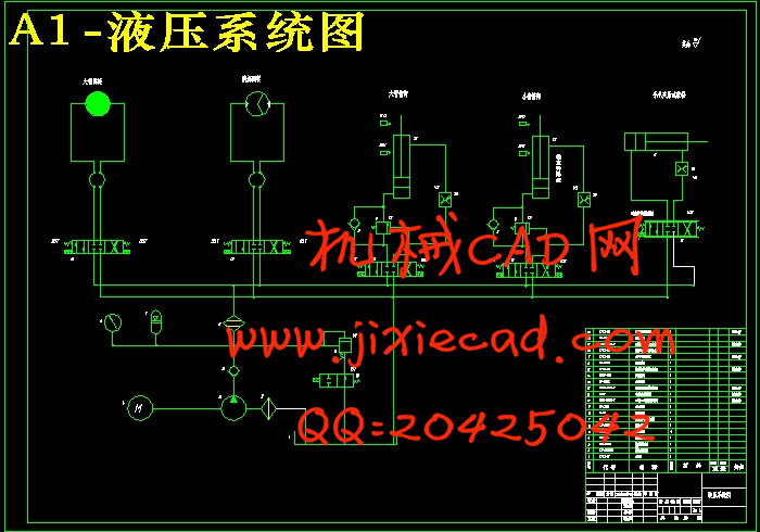
3.6 绘制液压系统图 39
3.6.1 计算和选择液压元件 40
3.6.2液压系统性能的验算 41
4 机械手控制系统设计 42
4.1 机械手的工艺过程 42
4.2 PLC 控制系统 43
4.3 PLC 控制系统程序设计 44
总结与展望 47
参考文献 48
致 谢 49