设计简介
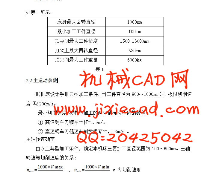
| 床身最大回转直径 | 1000mm |
| 最小加工工件直径 | 100mm |
| 顶尖间最大工件长度 | 1500-16000mm |
| 刀架上最大回转直径 | 630mm |
| 顶尖间最大工件重量 | 6000kg |
本论文首先介绍了我国数控机床发展的过程与现状 ,并分析了其存在的问题 ;对数控机床的发展趋势进行了探讨;并对CW61100E数控车床主轴箱传动系统进行了设计与计算。
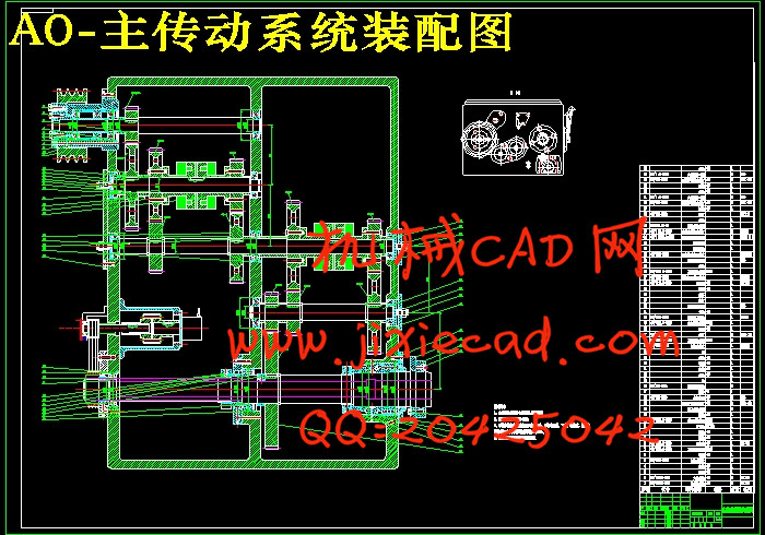
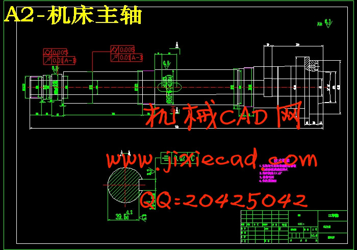
主轴箱有安装在精密轴承中的空心主轴和一系列变速齿轮组成。数控车床主轴可以获得在调速范围内的任意速度,以满足加工切削要求。
目前,数控车床的发展趋势是通过电气与机械装置进行无级变速。变频电机通过带传动和变速齿轮为主轴提供动力。通常变频电机调速范围3—5,难以满足主轴变速要求;串联变速齿轮则扩大了齿轮的变速范围 。
本设计将原来的带轮不卸荷结构变为了带轮卸荷结构,使输入轴在带处只受转矩,将轴上的径向力传动到车床机体上,改善了输入轴的受力情况。
关键词:主轴箱,无级调速,传动系统
Abstract
CNC lathe can not only outside the circle can be used for boring, facing, drilling and reaming. Compared with other kinds of machine tools, lathe is the most widely used in production.This paper introduces the process and current situation of the development of CNC machine tools in China, and analyzes its existing problems; the development trend of NC machine tool was discussed; and the CW61100E CNC lathe spindle box transmission system design and calculation.
The spindle box is composed of hollow spindle mounted in precision bearings and a set of transmission gears. Spindle CNC lathe can get any speed in speed range, to meet the machining requirements.
At present, the development trend of NC lathe is stepless speed change through the electrical and mechanical equipment. Variable frequency motor through the belt drive and gear to provide power for the spindle. Usually the frequency control of motor speed range of 3 - 5, to meet the requirements of spindle speed; series gear extends the range of gear transmission.
The design of the original belt wheel not unloading structure to belt wheel unloading structure, the input shaft with only by the shaft torque, radial force on the drive to the lathe body, improve the stress conditions of the input shaft.
Key Words: spindle box, stepless speed regulation, transmission system
目录
摘要 2
Abstract 3
1 绪论 6
2 设计计算 7
2.1机床的主参数 7
2.2主运动参数 7
1.3切削力的计算 8
3 主动参数参数的拟定 10
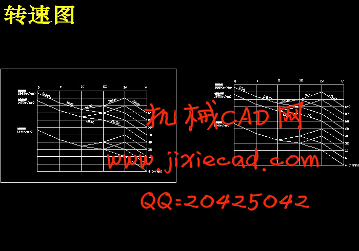
3.1主运动调速范围的确定、计算各轴计算转速、功率和转矩 10
3.2 主电动机的选择 11
4 变速结构的设计 13
4.1 主变速方案拟定 13
4.2 变速结构式、结构网的选择 13
4.2.1 确定变速组及各变速组中变速副的数目 13
4.2.2 结构网的拟定 14
4.2.3 结构式的拟定 14
4.2.4 结构式的拟定 14
4.2.5 确定各变速组变速副齿数 15
5 传动件的设计 16
5.1 带传动设计 16
5.2选择带型 17
5.3确定带轮的基准直径并验证带速 17
5.4确定中心距离、带的基准长度并验算小轮包角 18
5.5确定带的根数z 19
5.6确定带轮的结构和尺寸 19
5.7确定带的张紧装置 20
5.8计算压轴力 20
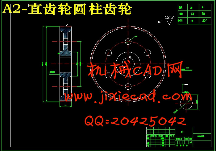
5.9 各变速组齿轮模数的确定和校核 22
5.9.1 齿轮模数的确定 22
5.9.2 齿宽的确定 26
5.9.3 齿轮结构的设计 26
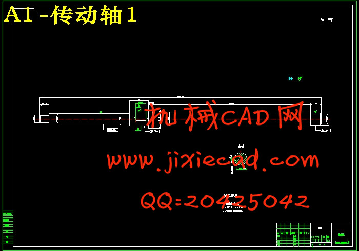
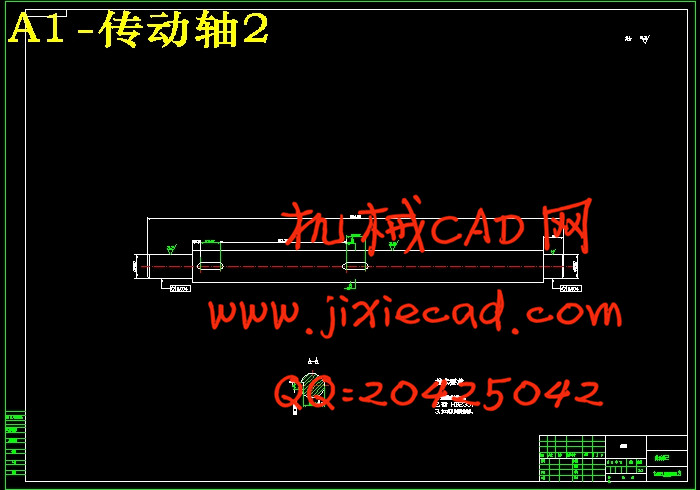
5.10 传动轴的直径估算 27
5.10.1 确定各轴转速 27
5.10.2传动轴直径的估算:确定各轴最小直径 28
5.10.3 键的选择 29
5.11 传动轴的校核 29
5.11.1 传动轴的校核 29
5.11.2 键的校核 30
5.12摩擦离合器的选择和计算 30
5.13 齿轮校验 33
5.13.1 校核a变速组齿轮 34
5.13.2 校核b变速组齿轮 35
5.13.3 校核c变速组齿轮 36
5.14 轴承的选用与校核 38
5.14.1 各轴轴承的选用 38
5.14.2 各轴轴承的校核 38
5.15主轴组件设计 39
6 结构设计 50
6.1 结构设计的内容、技术要求和方案 50
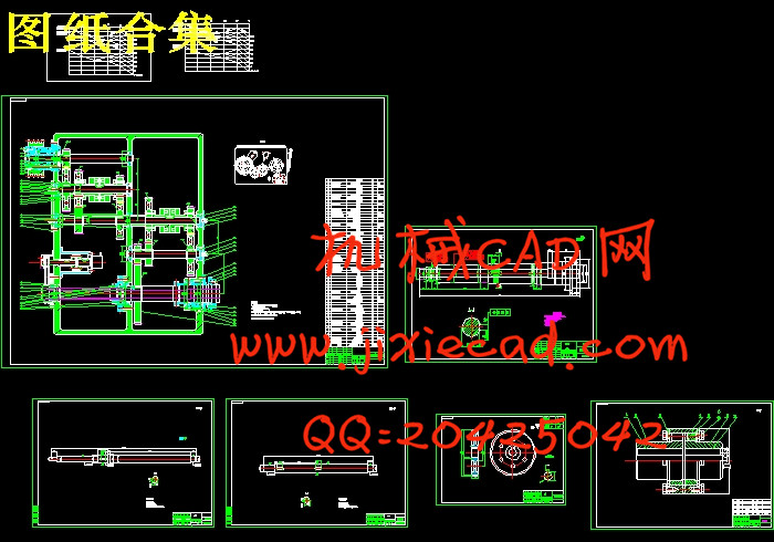
6.2 展开图及其布置 50
6.3 I轴(输入轴)的设计 51
6.4 齿轮块设计 52
6.5 传动轴的设计 53
6.6 主轴组件设计 54
6.6.1 各部分尺寸的选择 54
6.6.2 主轴材料和热处理 55
6.6.3 主轴轴承 55
6.6.4 主轴与齿轮的连接 57
6.6.5 润滑与密封 57
6.6.6 其他问题 58
7 总结和展望 59
7.1本文工作总结 59
7.2课题展望 60
参考文献 61
致 谢 63