设计简介
摘 要
减速机是一种动力传达机构,利用齿轮的速度转换器,将电机(马达)的回转数减速到 所要的回转数,并得到较大转矩的机构。在目前用于传递动力与运动的机构中,减速机的应 用范围相当广泛。几乎在各式机械的传动系统中都可以见到它的踪迹,从交通工具的船舶、 汽车、机车,建筑用的重型机具,机械工业所用的加工机具及自动化生产设备,到日常生活 中常见的家电,钟表等等.其应用从大动力的传输工作,到小负荷,精确的角度传输都可以见 到减速机的应用,且在工业应用上,减速机具有减速及增加转矩功能。因此广泛应用在速度 与扭矩的转换设备。减速机的作用主要有: 1)降速同时提高输出扭矩,扭矩输出比例按电机输出乘减速比,但要注意不能超出 减速机额定扭矩。 2)减速同时降低了负载的惯量,惯量的减少为减速比的平方。本设计为蜗杆减速器的设计及计算机辅助软件绘制。根据二维图纸建立三维模型,完成 设计过程。
本设计主要解决一下问题:
1. 确定原始数据和资料
2. 选定减速机的安装方式和类型
3. 初定各项工艺方法及参数
4. 确定传动级数
5. 确定几何参数
6. 整体方案
7. 校核
8. 润滑冷却计算
9. 确定减速机的附件
10. 绘制工程图
11. 三维图
关键词:减速器,齿轮传动,蜗杆
Abstract
Reducer is a power transmission mechanism, the gear speed converter, motor (motor) rotary number reduction to rotation number, and get a larger torque mechanism. At present is used to transfer power and movement mechanism, the use of a wide range of speed reducer. See it all in almost all kinds of mechanical transmission system, from the ship, transport vehicles, locomotives, heavy equipment for construction, processing machinery and automated production equipment used in industrial machinery, household appliances, common daily watches and so on. The application of power transmission from the work, to small load, accurate transmission angle can see the application of speed reducer, and in industrial applications, speed reducer has to slow down and increase torque function. It is widely used in speed and torque conversion equipment. The role of reducer are: 1) slow down while increasing the output torque, the torque output ratio by motor outputby slowdown, but be careful not to exceed the rated torque reducer. 2) speed and reduce the load inertia, inertia of deceleration than reduced to the square. The design for the software design and computer aided drawing a reducer. According to the 2D drawings to build a 3D model, complete the design process.
This design is mainly to solve the problem:
1 to determine the original data and information The installation mode and type
2 selected gear reducer
3 the initial process and parameters
4 drive series
5 determine the geometric parameters
6 overall plan
7 check
8 calculation of lubrication and cooling
9 reducer accessories
10 engineering drawing+3D design
Keywords: gear reducer, gear transmission, 3D
目 录
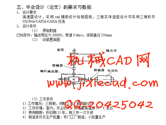
1 设计任务书 1
2 选择电动机 2
2.1 电动机类型和结构型式 2
2.2 电动机容量 2
2.3 电动机的转速 2
3 计算传动装置的运动和动力参数 4
4 蜗杆减速器的设计 5
4.1 选择蜗杆传动类型 5
4.2 选择材料 5
4.3 按齿面接触疲劳强度进行设计 5
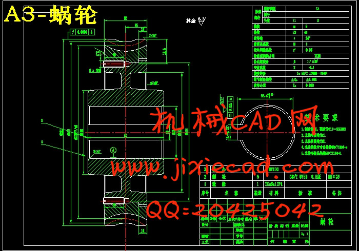
4.4 蜗杆与蜗轮的主要参数与几何尺寸 7
4.5 校核齿根弯曲疲劳强度 8
4.6 验算效率
4.7 精度等级公差和表面粗糙度的确定 9
4.8 热平衡核算 9
5 轴的设计计算 11
5.1 连轴器的设计计算 11
5.2 输入轴的设计计算 12
5.3 输出轴的设计计算 15
6 滚动轴承的选择及校核计算 18
6.1 计算输入轴轴承 18
6.2 计算输出轴轴承 21
7 键及联轴器连接的选择及校核计算 23
7.1 连轴器与电机连接采用平键连接 23
7.2 输入轴与联轴器连接采用平键连接 23
7.3 输出轴与联轴器连接用平键连接 24
7.4 输出轴与涡轮连接用平键连接 24
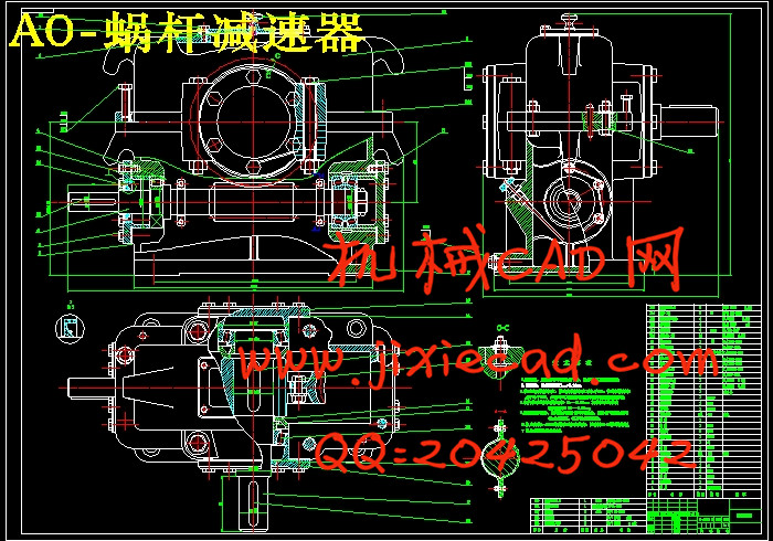
8 减速器结构与润滑的概要说明 25
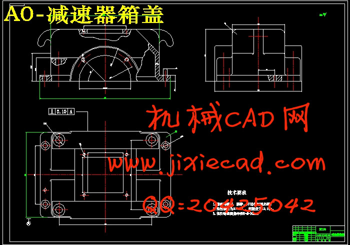
8.1 箱体的结构形式和材料 25
8.2 铸铁箱体主要结构尺寸和关系 25
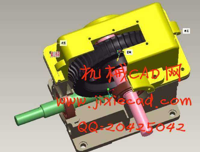
9 蜗杆蜗轮减速器三维建模 27
9.1 蜗杆建模 27
9.2 蜗轮建模 30
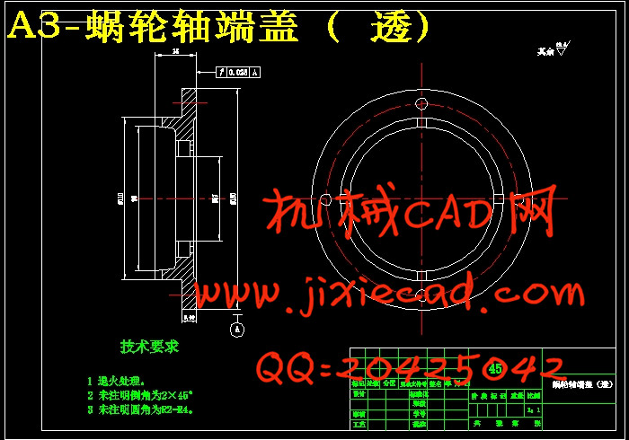
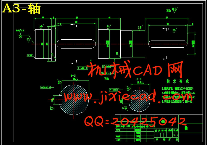
9.3 蜗轮轴建模 33
9.4 轴承建模 33
9.5 下箱体建模 34
9.6 上箱体建模 38
9.7 PROE/E装配 38
总论 43
参考文献 44