设计简介
摘
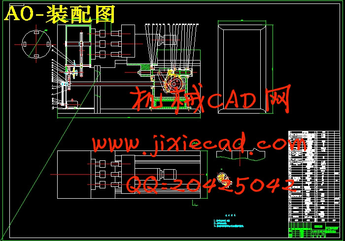
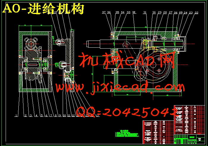
本次设计是对多工位机械转位装置的设计。在这里主要包括: 转位运动传动系统的设计、进给运动部位系统的设计这次毕业设计对设计工作的基本技能的训练,提高了分析和解决工程技术问题的能力,并为进行一般机械的设计创造了一定条件。整机电机通过带传动,带传动分配给两个方向的运动,一个是转位运动,一个是进给运动,从而带动整机运动,提高劳动生产率和生产自动化水平。更显示其优越性,有着广阔的发展前途。
本论文研究内容:
(1) 多工位机械转位装置总体结构设计。
(2) 多工位机械转位装置工作性能分析。
(3)电动机的选择。
(4) 多工位机械转位装置的传动系统、执行部件及机架设计。
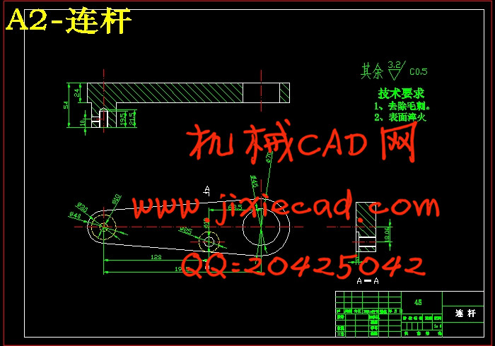
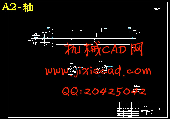
(5)对设计零件进行设计计算分析和校核。
(6)绘制整机装配图及重要部件装配图和设计零件的零件图。
关键词:多工位机械转位装置, 带传动,凸轮机构,间歇机构
Abstract
This design is the design of multi station mechanical transposition device. Here mainly includes: the design of this design, the transmission system of the transposition feed movement part of the system of graduation design on the design of the basic skills training, improve the analysis and the ability to solve engineering problems, and created a condition for general mechanical design.The motor through the belt drive, the belt drive is assigned to the movement in two directions, one is the transposition of movement, a feed motion, so as to drive the movement, improve labor productivity and automation level. But also show its superiority, there are broad prospects for the development.
The content of this paper:
(1) multi station mechanical transfer device structure design.
(2) analysis of multi station mechanical transfer device performance.
(3) the choice of motor.
(4) transmission system, execution unit and frame design of multi station mechanical transposition device.
(5) the design of parts design calculation and check.
(6) drawing machine assembly and important parts assembly drawings and parts drawings design.
Key Words: multi station mechanical transfer device, belt drive, cam, intermittent mechanism
目 录
摘 要 IIAbstract III
目 录 IV
第1章 绪论 1
1.1 专用机床的简介 1
1.2本课题国内外研究概况 2
1.3 机床设计的目的、要求 6
1.3.1 设计的目的 6
1.3.2 设计要求 6
第2章 总体方案确定 7
2.1拟定机构运动循环图 8
2.2 方案设计 8
2.3 进给运动采用凸轮机构 13
第3章 动力的选择 15
第4章 传动装置设计 17
4.1 确定传动装置的传动比 17
4.2 传动装置动力参数的计算 17
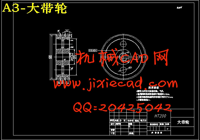
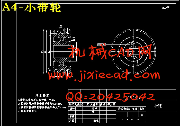
4.3 皮带轮的设计与计算 18
4.3.1 带型的选定 18
4.3.2 带轮直径与带速的确定 18
4.3.3 带的基准长度和轴间距的确定 19
4.3.4 验算小带轮的包角 19
4.3.5 确定V带根数 20
4.3.6 单根V带预紧力的计算 20
4.3.7 计算压轴力 20
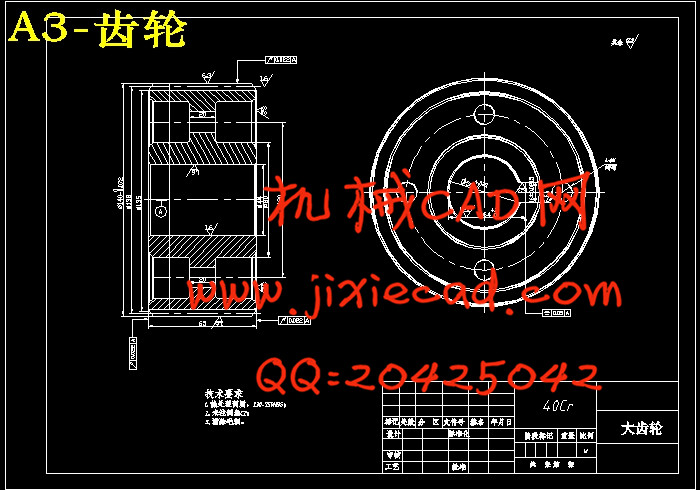
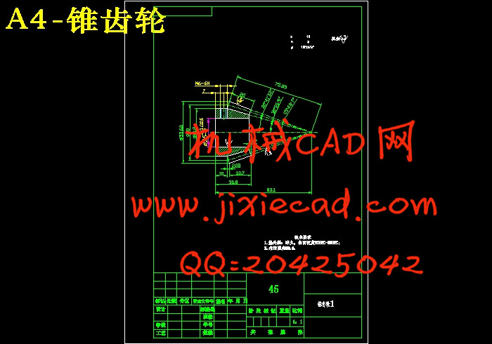
第5章 齿轮的设计与计算 21
5.1 材料的选择及许用应力的确定 21
5.2 按轮齿接触强度的计算 21
5.3 按齿根弯曲强度设计 23
第6章 槽轮机构凸轮机构的设计 25
6.1 槽轮机构设计 25
6.2 凸轮机构的设计 27
6.2.1 滚子半径的选择 28
6.2.2 压力角及其许用值 29
6.2.3 基圆半径的确定 30
6.2.4 凸轮机构的材料 31
第7章 轴的设计与计算 32
7.1 轴的材料选择 32
7.2 轴的最小直径确定 32
7.3 轴的结构设计 32
7.4 轴的校核 33
第8章 键连接选择 37
第9章 滚动轴承选用 38
结 论 40
致 谢 41
参考文献 42