设计简介
摘要
本次设计是柔性制造实验装置设计的设计。在这里主要包括:传动系统的设计、回转部位系统的设计、这次毕业设计对设计工作的基本技能的训练,提高了分析和解决工程技术问题的能力,并为进行一般机械的设计创造了一定条件。
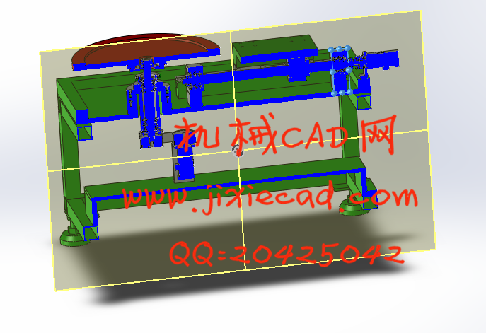
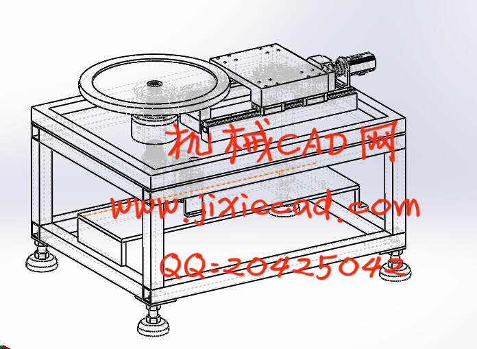
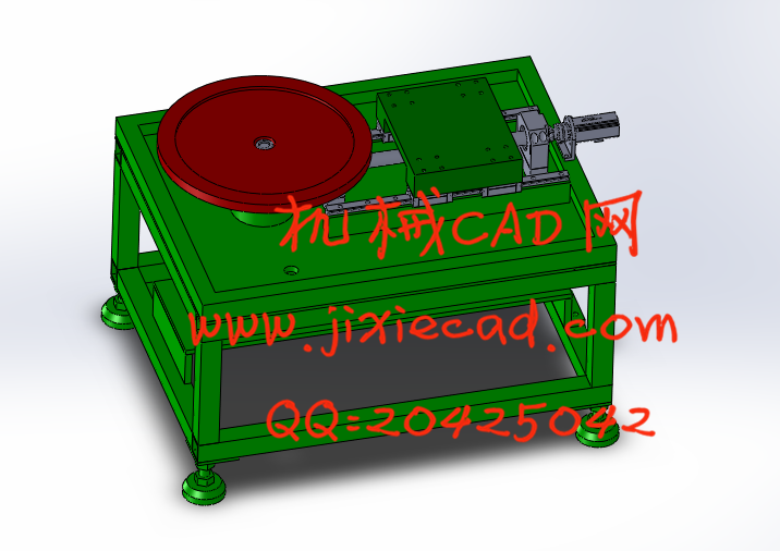
整机结构主要由电动机产生动力通过联轴器将需要的动力传递到丝杆上,丝杆带动丝杆螺母,从而带动整机运动,提高劳动生产率和生产自动化水平。更显示其优越性,有着广阔的发展前途。
本论文研究内容:
(1)总体结构设计。
(2) 柔性制造实验装置工作性能分析。
(3)电动机的选择。
(4) 柔性制造实验装置的传动系统、执行部件设计。
(5)对设计零件进行设计计算分析和校核。
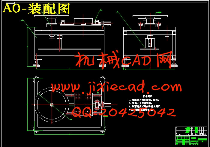
(6)绘制整机装配图及重要部件装配图和设计零件的零件图。
关键词:柔性制造实验装置, 联轴器,滚珠丝杠
Abstract
The experimental design is the flexible manufacturing system design design. Here include: transmission system design, turning parts of the system design, the graduation project design work on basic skills training to improve the ability to analyze and solve engineering problems, and for the general mechanical design to create a certain condition.The whole structure is mainly generated by the electric motor power the power needed to pass through the coupling to the screw, screw drive screw nut, thus boosting the overall campaign to raise labor productivity and production automation. More show its superiority, has a broad development prospects.
This thesis research:
(1) the overall structural design.
(2) Flexible manufacturing apparatus for analyzing the performance of the experimental work.
(3) Select the motor.
(4) Transmission flexible manufacturing test equipment, perform the component design.
(5) for the design of parts to design computational analysis and verification.
(6) to draw the whole assembly drawings and assembly drawings and designs important parts parts parts diagram.
Keywords: flexible manufacturing test equipment, couplings, ball
目录
摘 要 IIAbstract III
目 录 IV
1 绪论 1
1.1 柔性制造实验装置在我国的应用及发展趋势 1
1.2 本课题研究的内容及方法 1
1.2.1 主要的研究内容 1
1.2.2 设计要求 2
2 总体方案机构设计 3
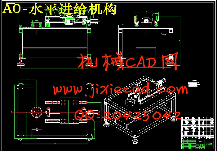
3 水平进给机构结构及传动设计 4
3.1 水平进给滚珠丝杆副的选择 5
3.1.1 导程确定 5
3.1.2 确定丝杆的等效转速 5
3.1.3 估计工作台质量及负重 5
3.1.4 确定丝杆的等效负载 5
3.1.5 确定丝杆所受的最大动载荷 6
3.1.6 精度的选择 7
3.1.7 选择滚珠丝杆型号 7
3.2 校核 7
3.2.1 临界压缩负荷验证 8
3.2.2 临界转速验证 9
3.2.3 丝杆拉压振动与扭转振动的固有频率 9
3.3 电机的选择 10
3.3.1 电机轴的转动惯量 10
3.3.2 电机扭矩计算 11
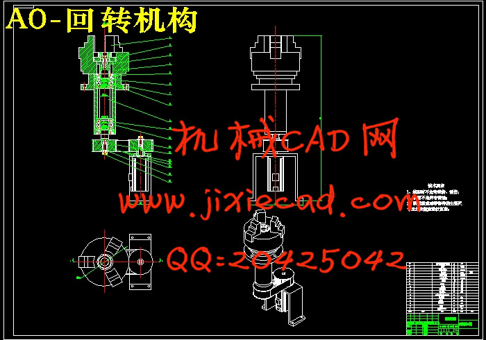
4 回转机构及主轴设计计算 13
4.1 电机的选择 13
4.2 同步带传动计算 13
4.2.1 同步带计算选型 13
4.2.2 同步带的主要参数(结构部分) 16
4.2.3 同步带的设计 18
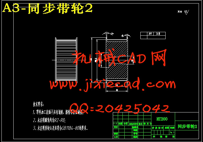
4.2.4 同步带轮的设计 19
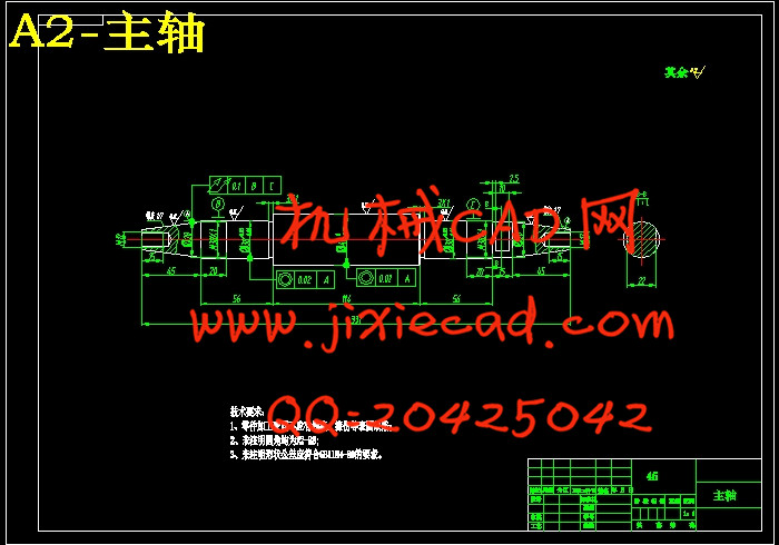
4.3 主轴组件设计计算 20
4.3.1 主轴的材料与热处理 20
4.3.2 主轴直径的选择 21
4.3.3 主轴前后轴承的选择 22
4.3.4 轴承的选型及校核 23
4.3.5 主轴前端悬伸量 24
4.3.6 主轴支承跨距 25
4.3.7 主轴结构图 26
5.4.8 主轴的校核 26
4.3.9 轴承寿命校核 29
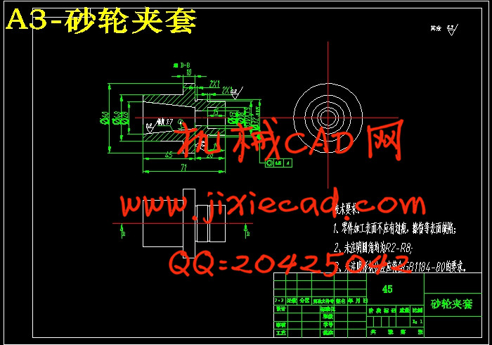
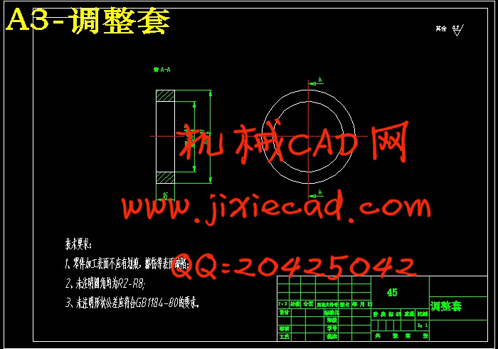
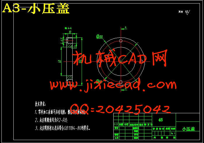
4.3.10 主轴组件中相关部件 29
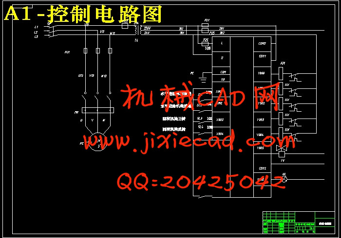
5 PLC控制部分设计 32
5.1 可编程序控制器的选择及工作过程 32
5.1.1 可编程序控制器的选择 32
5.1.2 可编程序控制器的工作过程 32
5.2 可编程序控制器的使用步骤 33
5.3可编程序控制器控制方案 34
5.3.1 控制系统的工作原理及控制要求 34
5.3.2.控制要求 34
5.4 PLC控制原理图设计 34
结论 36
致 谢 37
参考文献 39