设计简介
摘 要
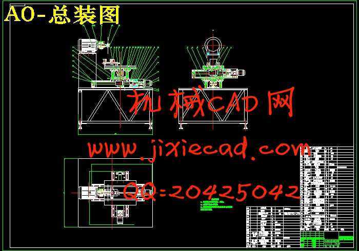
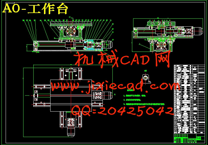
本次设计是对高精度零件切割加工专机的设计。在这里主要包括:传动系统的设计、装夹部位系统的设计、切割片主轴部位系统的设计这次毕业设计对设计工作的基本技能的训练,提高了分析和解决工程技术问题的能力,并为进行一般机械的设计创造了一定条件。整机电机通过联轴器连接着据刀片,工作台结构主要由电动机产生动力通过联轴器将需要的动力传递到丝杆上,丝杆带动丝杆螺母,从而带动整机运动,提高劳动生产率和生产自动化水平。更显示其优越性,有着广阔的发展前途。
本论文研究内容:
(1) 高精度零件切割加工专机总体结构设计。
(2) 高精度零件切割加工专机工作性能分析。
(3)电动机的选择。
(4) 高精度零件切割加工专机的传动系统、执行部件及机架设计。
(5)对设计零件进行设计计算分析和校核。
(6)绘制整机装配图及重要部件装配图和设计零件的零件图。
关键词:高精度零件切割加工专机, 联轴器,滚珠丝杠
Abstract
This design is a high-precision cutting plane design. Here include: basic skills driveline design, site design clamping system design cutting blade spindle part of the system design graduate design work training to improve the analysis and the ability to solve engineering problems, and for general mechanical design to create a certain condition.Machine motor is connected through a coupling according to the blades, the table structure is mainly generated by an electric motor powered by the power coupling will need to pass to the screw, screw drive screw nut, thus boosting the overall campaign to raise labor productivity and production automation. More show its superiority, has a broad development prospects.
This thesis research:
(1) high-precision cutting plane overall structural design.
(2) high-precision cutting plane performance analysis.
(3) Select the motor.
(4) high-precision cutting plane of the transmission system, the implementation of components and chassis designs.
(5) for the design of parts to design computational analysis and verification.
(6) to draw the whole assembly drawings and assembly drawings and designs important parts parts parts diagram.
Keywords: high-precision cutting plane, couplings, ball
目 录
摘 要 II
Abstract III
1 绪论 1
1.1高精度零件切割加工专机的研究现状 1
1.2高精度零件切割加工专机发展趋势 2
1.3本课题研究的内容及方法 4
1.3.1主要的研究内容和研究意义 4
1.3.2设计要求 4
1.3.3关键的技术问题 5
2 高精度零件切割加工专机总体结构设计 6
2.1设计的要求与数据 6
2.2 锯刀片选型 6
2.3 整机工作原理图 7
3 钢制金相切割X方向进给传动设计 7
3.1 X向滚珠丝杆副的选择 8
3.1.1导程确定 9
3.1.2确定丝杆的等效转速 9
3.1.3估计工作台质量及负重 9
3.1.4确定丝杆的等效负载 9
3.1.5确定丝杆所受的最大动载荷 10
3.1.6精度的选择 11
3.1.7选择滚珠丝杆型号 11
3.2校核 12
3.2.1 临界压缩负荷验证 12
3.2.2临界转速验证 13
3.2.3丝杆拉压振动与扭转振动的固有频率 13
3.3电机的选择 14
3.3.1电机轴的转动惯量 14
3.3.2电机扭矩计算 15
4 钢制金相切割Y方向进给传动设计 18
4.1 Y轴滚动导轨副的计算、选择 18
4.2 滚珠丝杠计算、选择 19
4.3 步进电机惯性负载的计算 22
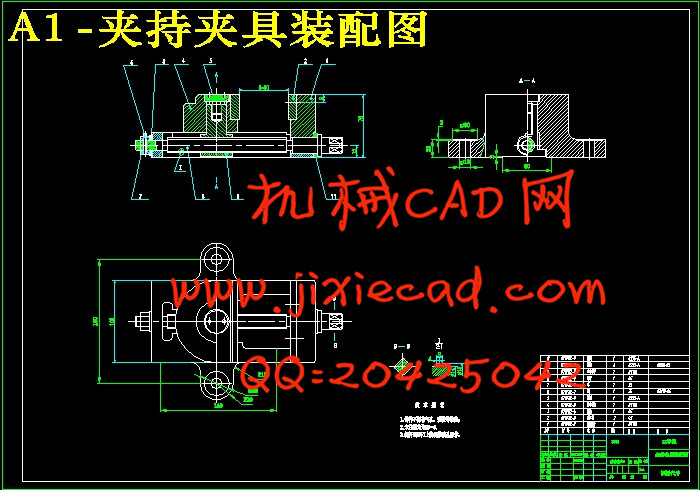
第3章 夹持工件夹具的设计 25
3.1 夹具结构 25
3.2 工作原理 25
各组成部分的设计 26
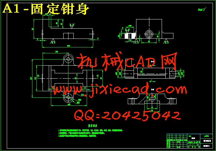
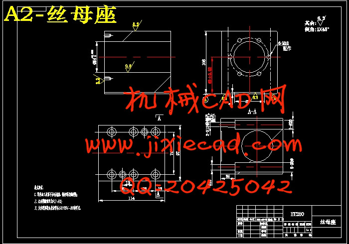
4.1 固定座的设计 26
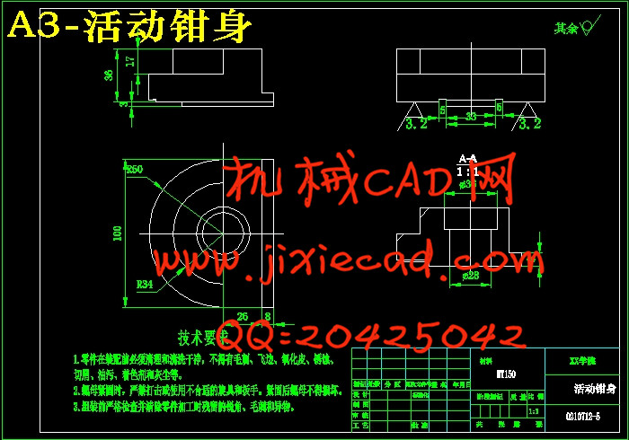
4.2 活动身的结构设计 26
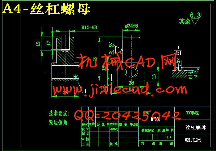
4.3 丝杠螺母的设计 27
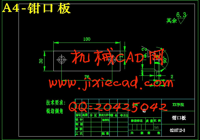
4.4 钳口板的结构设计 27
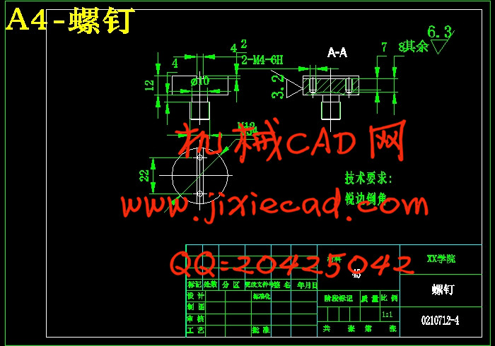
4.5 固定钳口板用螺钉的结构设计 28
4.6螺母的选择设计 28
4.7销的选择设计 29
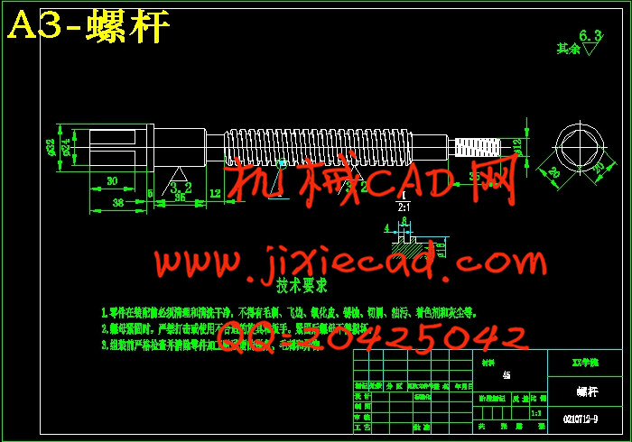
4.8螺杆的结构设计 29
4.9 螺杆的强度校核计算 30
4.10垫片的选择设计 30
结论 32
参考文献 33
致 谢 34