设计简介
摘 要
车床设计以及制造的发展速度是非常快的。从开始的只为了满足加工成形而要求刀具与工件之间的一些相对运动关系以及零件要达到一定的强度和刚度,发展到现在的高科技成果综合应用的现代车床设计,还包含计算机辅助设计(CAD)的应用。但目前车床主轴变速箱的设计仍然是以类比或者经验为基础的传统设计方法。因此,探索科学理论的应用,科学地分析处理经验、数据和资料,既能提高车床设计和制造水平,还可以使得设计方法更加现代化。
车床主轴变速箱设计是在学完基础课、技术基础课及相关专业课的基础上,结合车床传动部件设计所进行的综合训练。在本设计中要完成拟定参数,运动设计,动力计算,设计结构草图,轴和轴承的验算,主轴变速箱装配设计,编写设计计算说明书等内容。
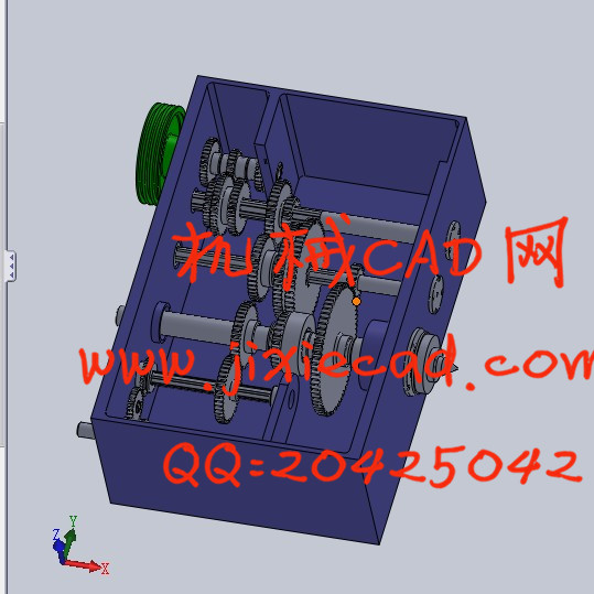
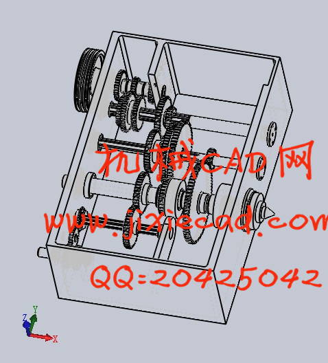
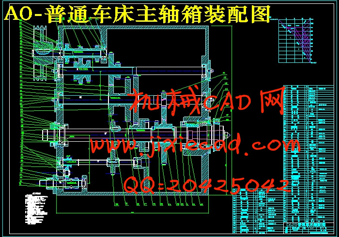
车床主轴变速箱的结构设计包括传动件(轴承,传动轴,带轮,离合器及制动器等),操纵机构,主轴部件,润滑密封系统和箱体及其联接件的结构设计与布置,用一张展开图和若干张截面图来表示。
【关键词】车床 主轴 变速箱
Abstract
Development of design and manufacturing of lathe speed is very fast. From the start in order to meet the requirements of forming some relationships and relative motion between tools and workpieces parts to achieve a certain degree of strength and stiffness, and development to the present design of comprehensive application of high-tech achievements of modern lathes, as well as computer-aided design (CAD) applications. But currently lathe spindle gearbox design is still based on analogy or experiences of traditional design methods. Therefore, exploring the application of scientific theory, scientific analysis and treatment experience, data and information, both to raise the level of design and manufacturing of lathe, and made the design more modern.
Lathe spindle gearbox design is based on the completion of courses, technical courses and specialized courses integrated training combination lathe designed transmission parts. To complete the development parameters in the design, motion design, calculation, design sketches, shaft and bearing calculation, spindle gearbox assembly design, write design specification, and so on.
Structure design of lathe spindle transmission, including the layout and structure design of transmission parts (bearings, shaft, pulley, clutch and brake, etc), control mechanism, spindle Assembly, lubrication and sealing system and casing design and their joints, using a map and a number of sections to represent.
【Key words】 lathe spindle gearbox
目 录
_Toc387442515
1 绪 论 4
1.1课题研究背景以及选题的意义 4
1.1.1课题研究背景 4
1.1.2选题的意义 4
1.1.3选题的目的 5
1.2研究的主要内容 5
1.2.1拟定主运动参数 5
1.2.2运动设计 5
1.2.3动力计算和结构草图设计 5
1.2.4传动件验算 6
1.2.5装配设计 6
1.2.6编写设计说明书 6
2.车床主要参数的确定 6
2.1 确定动力参数——主电机功率 7
2.2运动参数的确定 8
2.2.1 主轴最低和最高转速的确定 8
2.2.2 主轴转速数列的确定 8
3 传动系统设计 10
3.1 拟定主传动方案 10
3.2 选定传动结构拟定式 10
3.2.1 确定传动组和各传动组中传动副的数目 10
3.2.2 分配总降速比 11
3.3 确定皮带轮直径和齿轮齿数并拟定转速图 12
3.3.1拟定转速图: 12
3.3.2确定皮带轮直径 13
3.3.3 确定齿轮齿数 13
3.3.4 主轴转速系列的验算 14
3.3.5 传动系统图的拟定 16
3.4 确定各传动轴和齿轮的计算转速 16
3.4.1计算主轴转速 16
3.4.2计算各传动轴转速 16
3.4.3计算传动组各轴上最小齿轮转速 17
4 估算和验算传动件 17
4.1计算齿轮模数 17
4.1.1 计算各传动轴功率 17
4.1.2计算齿轮模数 18
4.1.3 计算各轴之间的中心距 19
4.2 计算三角带传动 19
4.2.1确定三角带速度 20
20
4.2.2确定中心距A 20
4.2.3确定三角带的计算长度L0及内周长LN 20
(4)确定实际中心距A 20
(5)验算小带轮包角α1 20
(6)确定三角带根数Z 21
4.3 估算传动轴和计算齿轮尺寸 21
4.3.1计算确定各轴的直径 21
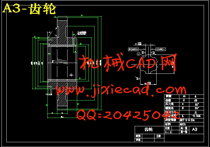
4.3.2 计算各齿轮的尺寸 22
5 主轴部件的验算 25
5.1验算主轴轴端位移ya 25
5.1.1主轴的支承简化 25
5.1.2主轴的受力分析 25
5.1.3确定切削力和传动力的作用类 26
5.1.4确定切削力P的大小 26
5.1.5确定a力的大小 27
5.2 验算前轴承的转角及寿命 27
5.2.1 验算前轴承处的转角θβ 27
5.2.2 验算前支承寿命 28
6设计主传动系统的结构 29
6.1 设计皮带轮及齿轮块 29
6.2 轴承的选择 29
6.2.1选择各轴承 29
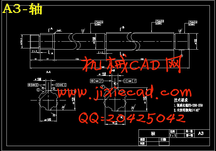
6.2.2 设计主轴 30
6.3设计箱体 30
6.4操纵机构的设计 30
6.5密封结构和润滑 30
总 结 32
致 谢 33
参考文献 34
车床设计以及制造的发展速度是非常快的。从开始的只为了满足加工成形而要求刀具与工件之间的一些相对运动关系以及零件要达到一定的强度和刚度,发展到现在的高科技成果综合应用的现代车床设计,还包含计算机辅助设计(CAD)的应用。但目前车床主轴变速箱的设计仍然是以类比或者经验为基础的传统设计方法。因此,探索科学理论的应用,科学地分析处理经验、数据和资料,既能提高车床设计和制造水平,还可以使得设计方法更加现代化。
车床主轴变速箱设计是在学完基础课、技术基础课及相关专业课的基础上,结合车床传动部件设计所进行的综合训练。在本设计中要完成拟定参数,运动设计,动力计算,设计结构草图,轴和轴承的验算,主轴变速箱装配设计,编写设计计算说明书等内容。
车床主轴变速箱的结构设计包括传动件(轴承,传动轴,带轮,离合器及制动器等),操纵机构,主轴部件,润滑密封系统和箱体及其联接件的结构设计与布置,用一张展开图和若干张截面图来表示。
【关键词】车床 主轴 变速箱
Abstract
Development of design and manufacturing of lathe speed is very fast. From the start in order to meet the requirements of forming some relationships and relative motion between tools and workpieces parts to achieve a certain degree of strength and stiffness, and development to the present design of comprehensive application of high-tech achievements of modern lathes, as well as computer-aided design (CAD) applications. But currently lathe spindle gearbox design is still based on analogy or experiences of traditional design methods. Therefore, exploring the application of scientific theory, scientific analysis and treatment experience, data and information, both to raise the level of design and manufacturing of lathe, and made the design more modern.
Lathe spindle gearbox design is based on the completion of courses, technical courses and specialized courses integrated training combination lathe designed transmission parts. To complete the development parameters in the design, motion design, calculation, design sketches, shaft and bearing calculation, spindle gearbox assembly design, write design specification, and so on.
Structure design of lathe spindle transmission, including the layout and structure design of transmission parts (bearings, shaft, pulley, clutch and brake, etc), control mechanism, spindle Assembly, lubrication and sealing system and casing design and their joints, using a map and a number of sections to represent.
【Key words】 lathe spindle gearbox
目 录
_Toc387442515
1 绪 论 4
1.1课题研究背景以及选题的意义 4
1.1.1课题研究背景 4
1.1.2选题的意义 4
1.1.3选题的目的 5
1.2研究的主要内容 5
1.2.1拟定主运动参数 5
1.2.2运动设计 5
1.2.3动力计算和结构草图设计 5
1.2.4传动件验算 6
1.2.5装配设计 6
1.2.6编写设计说明书 6
2.车床主要参数的确定 6
2.1 确定动力参数——主电机功率 7
2.2运动参数的确定 8
2.2.1 主轴最低和最高转速的确定 8
2.2.2 主轴转速数列的确定 8
3 传动系统设计 10
3.1 拟定主传动方案 10
3.2 选定传动结构拟定式 10
3.2.1 确定传动组和各传动组中传动副的数目 10
3.2.2 分配总降速比 11
3.3 确定皮带轮直径和齿轮齿数并拟定转速图 12
3.3.1拟定转速图: 12
3.3.2确定皮带轮直径 13
3.3.3 确定齿轮齿数 13
3.3.4 主轴转速系列的验算 14
3.3.5 传动系统图的拟定 16
3.4 确定各传动轴和齿轮的计算转速 16
3.4.1计算主轴转速 16
3.4.2计算各传动轴转速 16
3.4.3计算传动组各轴上最小齿轮转速 17
4 估算和验算传动件 17
4.1计算齿轮模数 17
4.1.1 计算各传动轴功率 17
4.1.2计算齿轮模数 18
4.1.3 计算各轴之间的中心距 19
4.2 计算三角带传动 19
4.2.1确定三角带速度
4.2.2确定中心距A 20
4.2.3确定三角带的计算长度L0及内周长LN 20
(4)确定实际中心距A 20
(5)验算小带轮包角α1 20
(6)确定三角带根数Z 21
4.3 估算传动轴和计算齿轮尺寸 21
4.3.1计算确定各轴的直径 21
4.3.2 计算各齿轮的尺寸 22
5 主轴部件的验算 25
5.1验算主轴轴端位移ya 25
5.1.1主轴的支承简化 25
5.1.2主轴的受力分析 25
5.1.3确定切削力和传动力的作用类 26
5.1.4确定切削力P的大小 26
5.1.5确定a力的大小 27
5.2 验算前轴承的转角及寿命 27
5.2.1 验算前轴承处的转角θβ 27
5.2.2 验算前支承寿命 28
6设计主传动系统的结构 29
6.1 设计皮带轮及齿轮块 29
6.2 轴承的选择 29
6.2.1选择各轴承 29
6.2.2 设计主轴 30
6.3设计箱体 30
6.4操纵机构的设计 30
6.5密封结构和润滑 30
总 结 32
致 谢 33
参考文献 34