设计简介
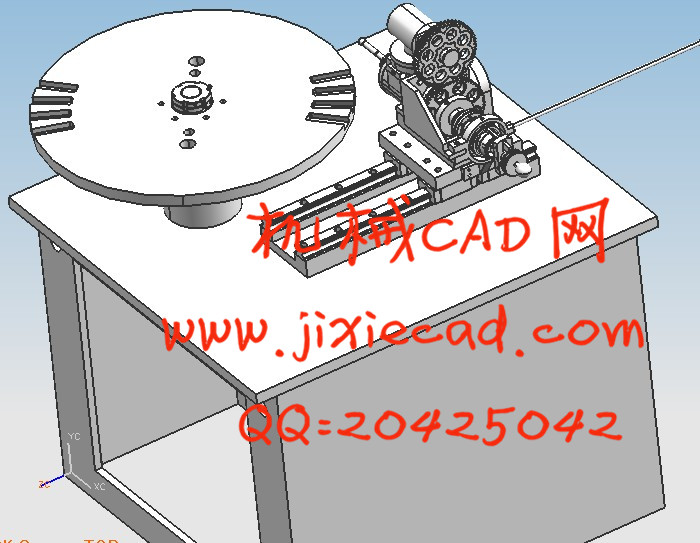
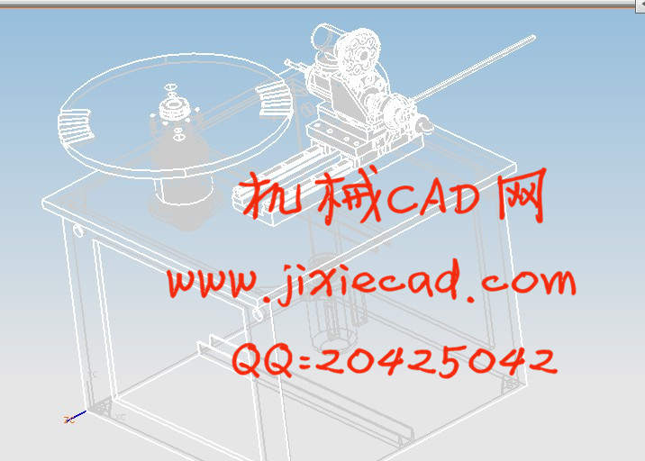
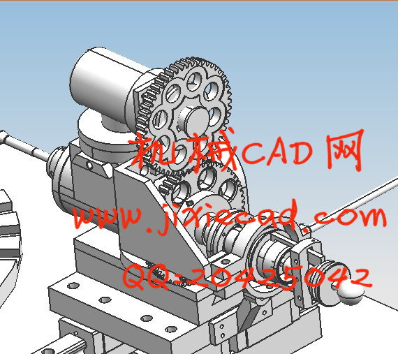
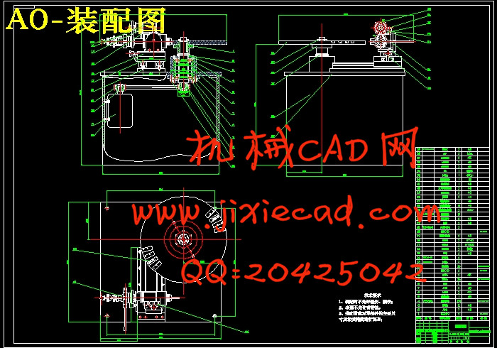
首先针对拉花机进行总体方案设计,进而确定拉花机的总体布局,随后,对主轴组件进行设计。介绍了主轴的工作原理及关键技术。然后,确定了合理的主轴总体结构,分别对主轴的各零部件作了设计,产生了装配图、零件图与设计说明书等设计文档。最后,对主轴的旋转轴和轴承进行了详细的分析和校核,计算表明,该主轴设计符合要求。
对拉花机夹具内有合理的定位及夹紧,能够实现沿刀具径向和轴向微调,能够沿刀具轴向和径向做精确调整,能够通过简便方法实现不同直径工件的装夹定位,经过设计对拉花机进行了优化设计和合理设计,取得了良好的效果。
关键词: 拉花机,主轴组件,主轴,轴承,带轮
Firstly, the overall scheme design for garland machine, which will determine the overall layout of the machine, garland, the spindle components of the design. This paper introduces the working principle and key technology of spindle. Then, the main structure reasonable, the main components were designed, produced the assembly drawing, part drawing and design specifications and design documents. Finally, the rotation of the spindle shaft and bearing are analyzed and checked, detailed calculation shows that, the spindle is designed to meet the requirements of.
A positioning and clamping the drawloom clamp, can realize the tool along the radial and axial adjustment, accurate adjustment tool can do along the axial and radial, through a simple method for different diameter of workpiece clamping and positioning, through the design of the optimization design and the reasonable design of the drawloom, achieved good results.
Keywords: garland machine, spindle, spindle, bearing, pulley
目 录
1 绪论 1
1.1 概述 1
1.2 课题研究的目的和意义 1
1.3 国内外研究现状 2
2 拉花机的总体参数计算 4
2.1 毕业设计内容及要求 4
2.2 总体设计轮廓 4
3 电机至回转工作台之间带传动计算 5
3.1 电动机的选型 5
3.2 带传动设计 6
3.2.1 选择带型 7
3.2.2 确定带轮的基准直径并验证带速 8
3.2.3 确定中心距离、带的基准长度并验算小轮包角 8
3.2.4 确定带的根数z 9
3.2.5 确定带轮的结构和尺寸 9
3.2.6确定带的张紧装置 10
3.3 带轮1上键的选择与校核 11
3.4 带轮2上键的选择与校核 13
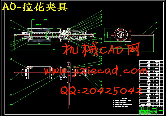
4 拉花工序夹具及其传动设计 15
4.1 夹具的设计要点 15
4.2 定位机构 15
4.3 夹紧机构 15
4.4 零件的夹具的加工误差分析 17
4.5 确定夹具体结构尺寸和总体结构 17
4.6 零件的专用夹具简单使用说明 18
4.7 夹具部位的齿轮的设计计算 19
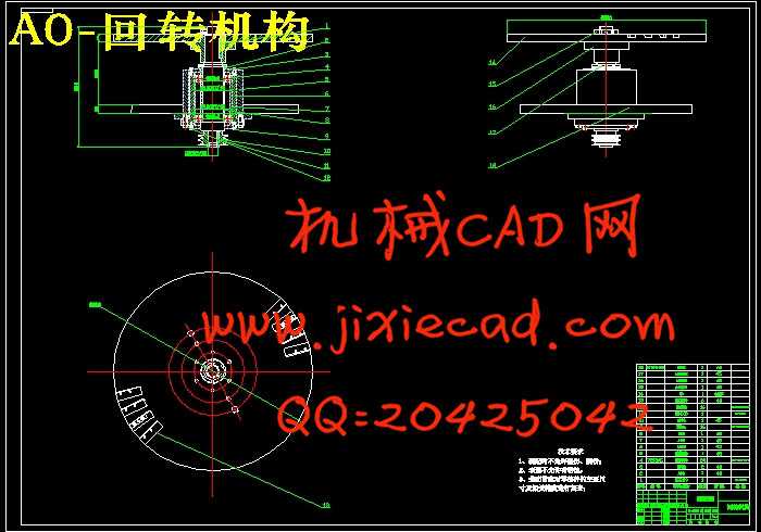
5 回转工作台组件要求与设计计算 24
5.1 主轴的基本要求 24
5.1.1 旋转精度 24
5.1.2 刚度 24
5.1.3 抗振性 25
5.1.4 温升和热变形 25
5.1.5 耐磨性 26
5.2 主轴组件的布局 26
5.3 主轴结构的初步拟定 29
5.4 主轴的材料与热处理 29
5.5 主轴的技术要求 30
5.6 主轴直径的选择 31
5.7 主轴前后轴承的选择 31
5.8 轴承的选型及校核 32
5.9 主轴前端悬伸量 34
5.10 主轴支承跨距 35
5.11 主轴组件的验算 35
5.11.1 支承的简化 35
5.11.2 主轴的挠度 36
5.11.3 主轴倾角 37
5.12 主轴机构相关部件 38
5.12.1 主轴轴承的润滑 38
5.12.2 主轴组件的密封 38
5.12.3 轴肩挡圈 39
5.12.4 挡圈 39
5.12.5 圆螺母 39
5.12.6 挠度、转角、锁紧力的计算及校核 39
5.12.7 直线滚动导轨副的计算、选择 41
结束语 44
致 谢 45
参考文献 46
对拉花机夹具内有合理的定位及夹紧,能够实现沿刀具径向和轴向微调,能够沿刀具轴向和径向做精确调整,能够通过简便方法实现不同直径工件的装夹定位,经过设计对拉花机进行了优化设计和合理设计,取得了良好的效果。
关键词: 拉花机,主轴组件,主轴,轴承,带轮
Firstly, the overall scheme design for garland machine, which will determine the overall layout of the machine, garland, the spindle components of the design. This paper introduces the working principle and key technology of spindle. Then, the main structure reasonable, the main components were designed, produced the assembly drawing, part drawing and design specifications and design documents. Finally, the rotation of the spindle shaft and bearing are analyzed and checked, detailed calculation shows that, the spindle is designed to meet the requirements of.
A positioning and clamping the drawloom clamp, can realize the tool along the radial and axial adjustment, accurate adjustment tool can do along the axial and radial, through a simple method for different diameter of workpiece clamping and positioning, through the design of the optimization design and the reasonable design of the drawloom, achieved good results.
Keywords: garland machine, spindle, spindle, bearing, pulley
目 录
1 绪论 1
1.1 概述 1
1.2 课题研究的目的和意义 1
1.3 国内外研究现状 2
2 拉花机的总体参数计算 4
2.1 毕业设计内容及要求 4
2.2 总体设计轮廓 4
3 电机至回转工作台之间带传动计算 5
3.1 电动机的选型 5
3.2 带传动设计 6
3.2.1 选择带型 7
3.2.2 确定带轮的基准直径并验证带速 8
3.2.3 确定中心距离、带的基准长度并验算小轮包角 8
3.2.4 确定带的根数z 9
3.2.5 确定带轮的结构和尺寸 9
3.2.6确定带的张紧装置 10
3.3 带轮1上键的选择与校核 11
3.4 带轮2上键的选择与校核 13
4 拉花工序夹具及其传动设计 15
4.1 夹具的设计要点 15
4.2 定位机构 15
4.3 夹紧机构 15
4.4 零件的夹具的加工误差分析 17
4.5 确定夹具体结构尺寸和总体结构 17
4.6 零件的专用夹具简单使用说明 18
4.7 夹具部位的齿轮的设计计算 19
5 回转工作台组件要求与设计计算 24
5.1 主轴的基本要求 24
5.1.1 旋转精度 24
5.1.2 刚度 24
5.1.3 抗振性 25
5.1.4 温升和热变形 25
5.1.5 耐磨性 26
5.2 主轴组件的布局 26
5.3 主轴结构的初步拟定 29
5.4 主轴的材料与热处理 29
5.5 主轴的技术要求 30
5.6 主轴直径的选择 31
5.7 主轴前后轴承的选择 31
5.8 轴承的选型及校核 32
5.9 主轴前端悬伸量 34
5.10 主轴支承跨距 35
5.11 主轴组件的验算 35
5.11.1 支承的简化 35
5.11.2 主轴的挠度 36
5.11.3 主轴倾角 37
5.12 主轴机构相关部件 38
5.12.1 主轴轴承的润滑 38
5.12.2 主轴组件的密封 38
5.12.3 轴肩挡圈 39
5.12.4 挡圈 39
5.12.5 圆螺母 39
5.12.6 挠度、转角、锁紧力的计算及校核 39
5.12.7 直线滚动导轨副的计算、选择 41
结束语 44
致 谢 45
参考文献 46