设计简介
摘 要
本次设计是对高速电火花打小孔机床的设计。在这里主要包括: X轴传动系统的设计、Y轴传动系统的设计、Z轴传动系统的设计、动力头系统的设计。这次毕业设计对设计工作的基本技能的训练,提高了分析和解决工程技术问题的能力,并为进行一般机械的设计创造了一定条件。
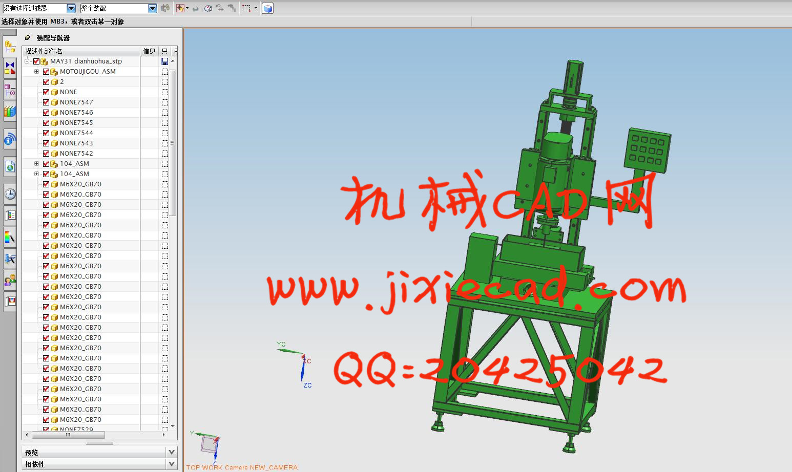
整机结构主要由电动机产生动力通过联轴器将需要的动力传递到丝杆上,丝杆带动丝杆螺母,从而带动整机装置运动,提高劳动生产率和生产自动化水平。更显示其优越性,有着广阔的发展前途。
本论文研究内容:
(1) 高速电火花打小孔机床总体结构设计。
(2) 高速电火花打小孔机床工作性能分析。
(3)电动机的选择。
(4) 高速电火花打小孔机床的传动系统、执行部件设计。
(5)对设计零件进行设计计算分析和校核。
(6)运用计算机辅助设计,对设计的零件进行三维建模。
(7)绘制整机装配图及重要部件装配图和设计零件的零件图。
关键词:高速电火花打小孔机床, 联轴器,滚珠丝杠
Abstract
This design is the design of high-speed electric spark pinhole machine. Here mainly includes: the X axis drive system design, Y axis drive system design, Z axis drive system design, power system design. The graduation design on the design of the basic skills training, enhancing the analysis and to solve engineering problems, and create a certain condition for general mechanical design.The structure is mainly produced by the motor power through the coupling will need to transfer the power to the screw rod, the screw rod drives the screw rod nut, so as to drive the device, improve labor productivity and automation level of production. But also show its superiority, there are broad prospects for the development.
The research of this thesis:
(1) a small overall structure design of high-speed electric spark machine tool.
(2) analysis of small hole machine tool working performance of high speed electric spark hit.
(3) the choice of motor.
(4) the design of transmission system, execute parts of the high-speed electric spark eyeleting machine.
(5) the design of components for the design calculation and check.
(6) the use of computer aided design, 3D modeling on Design of parts.
(7) to draw the assembly drawing and parts assembly diagram and parts diagram design.
Keywords: high speed EDM drilling holes on the machine, coupling, ball screw
Abstract III
目 录 IV
1 绪论 1
1.1 电火花加工简述 1
1.2 电火花加工工作原理 1
1.3 电火花加工特性 2
1.4 电火花加工主要特点 2
1.5 本课题研究的内容及方法 4
1.5.1 主要的研究内容 4
1.5.2 设计要求 4
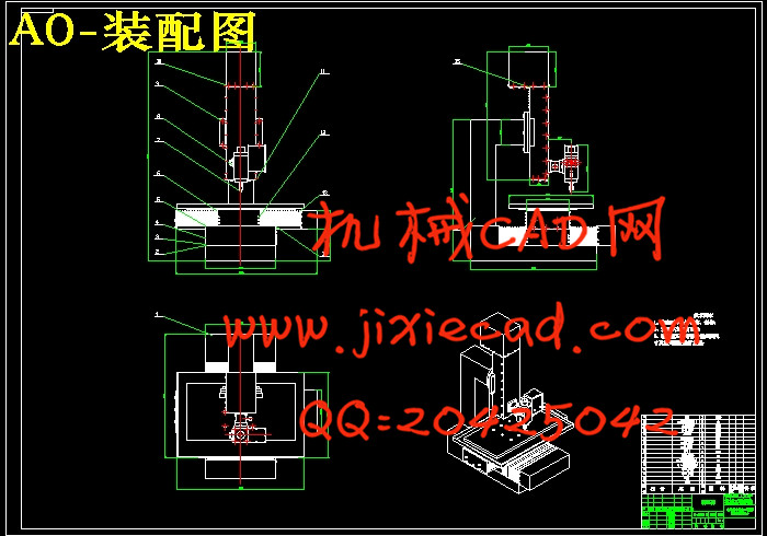
2 高速电火花打小孔机床总体设计 6
2.1 总体概述 6
2.2 技术参数 6
2.3 设计原理 7
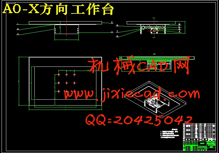
3 X轴进给机构结构及传动设计 8
3.1 拟定X轴进给方案图 8
3.2 最大工作载荷的计算 8
3.3 最大动载荷的计算 9
3.4 滚珠丝杠螺母副的选型 9
3.5 滚珠丝杠副的支承方式 10
3.6 传动效率的计算 10
3.7 刚度的验算 10
3.8 稳定性校核 11
3.9 临界转速的验证 11
3.10 步进电机的计算和选用 12
3.10.1 转动惯量的计算 12
3.10.2 电机力矩的计算 13
3.11 步进电机的选择 15
4 Y向进给机构设计计算 17
4.1 Y向传动系统图 17
4.2 Y向进给伺服系统机械部分计算与校核 17
4.2.1 杆螺母副的设计、计算与选型 18
4.2.2 步进电机的计算,校核和选型 21
4.2.3 导轨副的计算、选择 27
4.2.4 轴承的选择 29
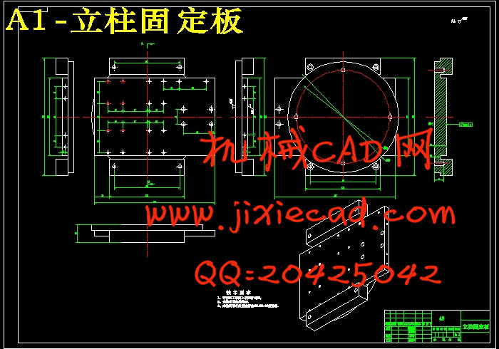
5 Z轴进给机构结构及传动设计 31
5.1 Z轴进给滚珠丝杆副的选择 31
5.1.1 导程确定 31
5.1.2 确定丝杆的等效转速 31
5.1.3 估计工作台质量及负重 31
5.1.4 确定丝杆的等效负载 32
5.1.5 确定丝杆所受的最大动载荷 32
5.1.6 精度的选择 33
5.1.7 选择滚珠丝杆型号 33
5.2 校核 34
5.2.1 临界压缩负荷验证 34
5.2.2 临界转速验证 35
5.2.3 丝杆拉压振动与扭转振动的固有频率 35
5.3 电机的选择 36
5.3.1 电机轴的转动惯量 36
5.3.2 电机扭矩计算 37
6 动力头主轴设计计算 40
6.1 电机的选择 40
6.2 同步带传动计算 40
6.2.1 同步带计算选型 40
6.2.2 同步带的设计 44
6.3 主轴组件设计计算 44
6.3.1 主轴的材料与热处理 44
6.3.2 主轴直径的选择 45
6.3.3 主轴前后轴承的选择 46
6.3.4 轴承的选型及校核 46
6.3.5 主轴前端悬伸量 48
6.3.6 主轴支承跨距 49
6.3.7 主轴的校核 49
6.3.8 轴承寿命校核 52
6.3.9 主轴组件中相关部件 53
结论 55
致 谢 56
参考文献 57