设计简介
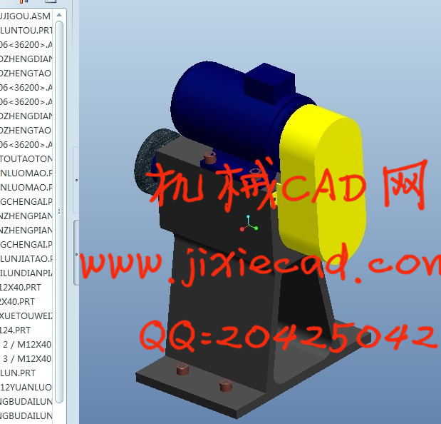
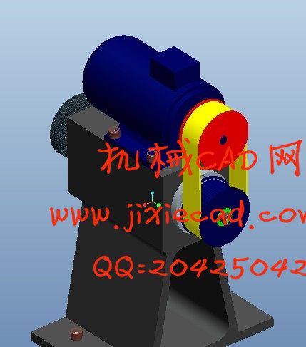
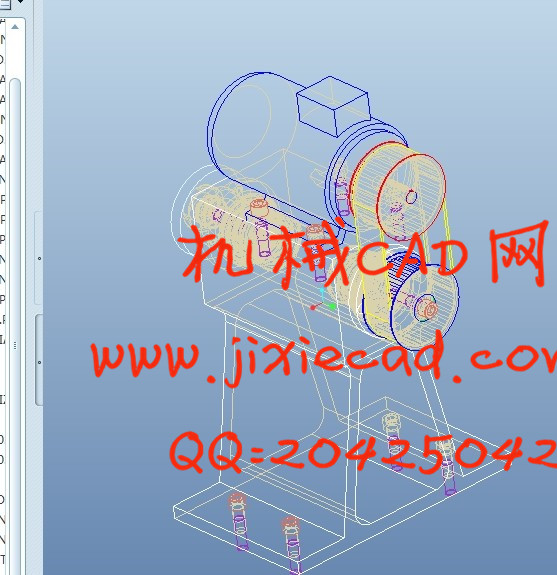
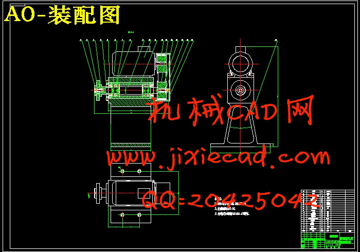
首先针对特殊磨头进行总体方案设计,进而确定特殊磨头的总体布局,随后,对主轴组件进行设计。介绍了主轴的工作原理及关键技术。然后,确定了合理的主轴总体结构,分别对主轴的各零部件作了设计,产生了装配图、零件图与设计说明书等设计文档。最后,对主轴的旋转轴和轴承进行了详细的分析和校核,计算表明,该主轴设计符合要求。
最后选取了一种典型的零件带轮作为研究对象,介绍车削工艺的设计方法和相关的工艺选择原则;并分别对带轮零件分析它的工艺设计、加工过程及加工工艺难点,解决了这几类零件的主要工艺要点问题并给出具体的零件加工工序,为其它同类零件的加工提供依据。
关键词: 特殊磨头,主轴组件,主轴,轴承,带轮
Abstract
Firstly, the overall scheme design for special grinding head, which will determine the overall layout, then special grinding head, the design of the main components. This paper introduces the working principle and key technology of spindle. Then, the main structure reasonable, the main components were designed, produced the assembly drawing, part drawing and design specifications and design documents. Finally, the rotation of the spindle shaft and bearing are analyzed and checked, detailed calculation shows that, the spindle is designed to meet the requirements of.
Finally, as a typical part with wheels as the research object, introduces the design method of turning process and related process selection principle; and analyzes the difficult process of process design, the machining process and machining on the belt wheel parts, the main technological points of these parts of the problem and gives the specific machining process, provide the basis for the processing of other similar parts.
Keywords :special grinding head, spindle assembly, spindle, bearing, pulley
目 录
1 绪论 1
1.1 概述 1
1.2 课题研究的目的和意义 1
1.3 国内外研究现状 2
2 特殊磨头的参数计算 4
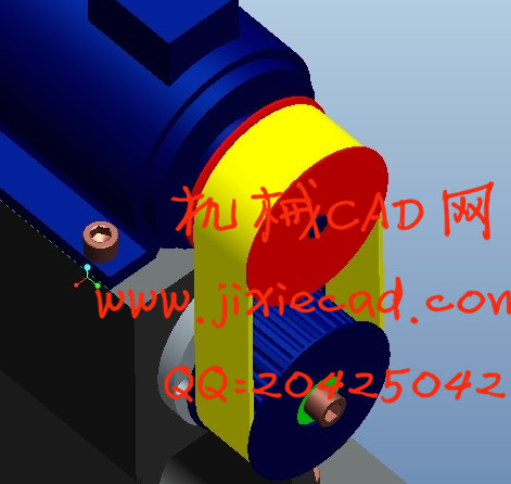
2.1 同步带的概述 4
2.1.1 同步带介绍 4
2.1.2 同步带的特点 4
2.1.3 同步带传动的主要失效形式 5
2.1.4 同步带传动的设计准则 7
2.1.5 同步带分类 7
2.2 减速电机介绍 8
2.3 特殊磨头电机的选取 9
2.4 同步带传动计算 11
2.4.1 同步带计算选型 11
2.4.2 同步带的主要参数(结构部分) 14
2.4.3 同步带的设计 16
2.4.4 同步带轮的设计 17
3 主轴组件要求与设计计算 19
3.1 主轴的基本要求 19
3.1.1 旋转精度 19
3.1.2 刚度 19
3.1.3 抗振性 20
3.1.4 温升和热变形 20
3.1.5 耐磨性 21
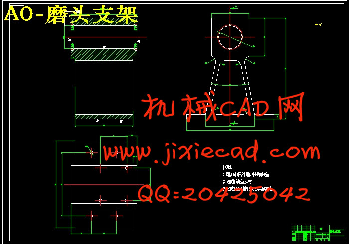
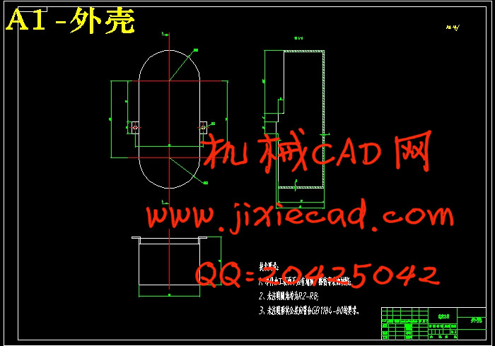
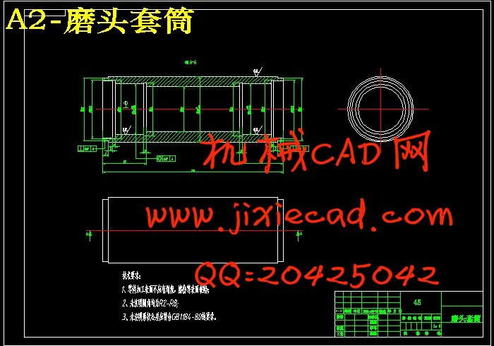
3.2 主轴组件的布局 21
3.3 主轴结构的初步拟定 24
3.4 主轴的材料与热处理 24
3.5 主轴的技术要求 25
3.6 主轴直径的选择 26
3.7 主轴前后轴承的选择 26
3.8 轴承的选型及校核 27
3.9 主轴前端悬伸量 30
3.10 主轴支承跨距 30
3.11 主轴结构图 31
3.12 主轴组件的验算 31
3.12.1 支承的简化 31
3.12.2 主轴的挠度 32
3.12.3 主轴倾角 33
4 磨头机构相关部件 35
4.1 主轴轴承的润滑 35
4.2 主轴组件的密封 35
4.2.1 主轴组件密封装置的类型 35
4.2.2 主轴组件密封装置的选择 35
4.3 轴肩挡圈 36
4.4 挡圈 36
4.5 圆螺母 36
4.6 支架校核计算 37
4.7 挠度、转角、锁紧力的计算及校核 37
4.7.1 挠度的计算 38
4.7.2 转角的计算 38
4.7.3 压板处螺栓的选择及校核 38
5 主要零件的加工工艺 40
5.1 零件图样分析 40
5.2 零件工序和装夹方式的确定 41
5.3 加工顺序的确定 41
5.4 进给路线的确定 41
5.5 夹具的选择 42
5.6 刀具的选择 42
5.7 切削用量的选择 43
5.8 加工所需工、量具 43
5.9 加工工艺卡片 43
结束语 45
致 谢 46
参考文献 47
最后选取了一种典型的零件带轮作为研究对象,介绍车削工艺的设计方法和相关的工艺选择原则;并分别对带轮零件分析它的工艺设计、加工过程及加工工艺难点,解决了这几类零件的主要工艺要点问题并给出具体的零件加工工序,为其它同类零件的加工提供依据。
关键词: 特殊磨头,主轴组件,主轴,轴承,带轮
Abstract
Firstly, the overall scheme design for special grinding head, which will determine the overall layout, then special grinding head, the design of the main components. This paper introduces the working principle and key technology of spindle. Then, the main structure reasonable, the main components were designed, produced the assembly drawing, part drawing and design specifications and design documents. Finally, the rotation of the spindle shaft and bearing are analyzed and checked, detailed calculation shows that, the spindle is designed to meet the requirements of.
Finally, as a typical part with wheels as the research object, introduces the design method of turning process and related process selection principle; and analyzes the difficult process of process design, the machining process and machining on the belt wheel parts, the main technological points of these parts of the problem and gives the specific machining process, provide the basis for the processing of other similar parts.
Keywords :special grinding head, spindle assembly, spindle, bearing, pulley
目 录
1 绪论 1
1.1 概述 1
1.2 课题研究的目的和意义 1
1.3 国内外研究现状 2
2 特殊磨头的参数计算 4
2.1 同步带的概述 4
2.1.1 同步带介绍 4
2.1.2 同步带的特点 4
2.1.3 同步带传动的主要失效形式 5
2.1.4 同步带传动的设计准则 7
2.1.5 同步带分类 7
2.2 减速电机介绍 8
2.3 特殊磨头电机的选取 9
2.4 同步带传动计算 11
2.4.1 同步带计算选型 11
2.4.2 同步带的主要参数(结构部分) 14
2.4.3 同步带的设计 16
2.4.4 同步带轮的设计 17
3 主轴组件要求与设计计算 19
3.1 主轴的基本要求 19
3.1.1 旋转精度 19
3.1.2 刚度 19
3.1.3 抗振性 20
3.1.4 温升和热变形 20
3.1.5 耐磨性 21
3.2 主轴组件的布局 21
3.3 主轴结构的初步拟定 24
3.4 主轴的材料与热处理 24
3.5 主轴的技术要求 25
3.6 主轴直径的选择 26
3.7 主轴前后轴承的选择 26
3.8 轴承的选型及校核 27
3.9 主轴前端悬伸量 30
3.10 主轴支承跨距 30
3.11 主轴结构图 31
3.12 主轴组件的验算 31
3.12.1 支承的简化 31
3.12.2 主轴的挠度 32
3.12.3 主轴倾角 33
4 磨头机构相关部件 35
4.1 主轴轴承的润滑 35
4.2 主轴组件的密封 35
4.2.1 主轴组件密封装置的类型 35
4.2.2 主轴组件密封装置的选择 35
4.3 轴肩挡圈 36
4.4 挡圈 36
4.5 圆螺母 36
4.6 支架校核计算 37
4.7 挠度、转角、锁紧力的计算及校核 37
4.7.1 挠度的计算 38
4.7.2 转角的计算 38
4.7.3 压板处螺栓的选择及校核 38
5 主要零件的加工工艺 40
5.1 零件图样分析 40
5.2 零件工序和装夹方式的确定 41
5.3 加工顺序的确定 41
5.4 进给路线的确定 41
5.5 夹具的选择 42
5.6 刀具的选择 42
5.7 切削用量的选择 43
5.8 加工所需工、量具 43
5.9 加工工艺卡片 43
结束语 45
致 谢 46
参考文献 47