设计简介
摘 要
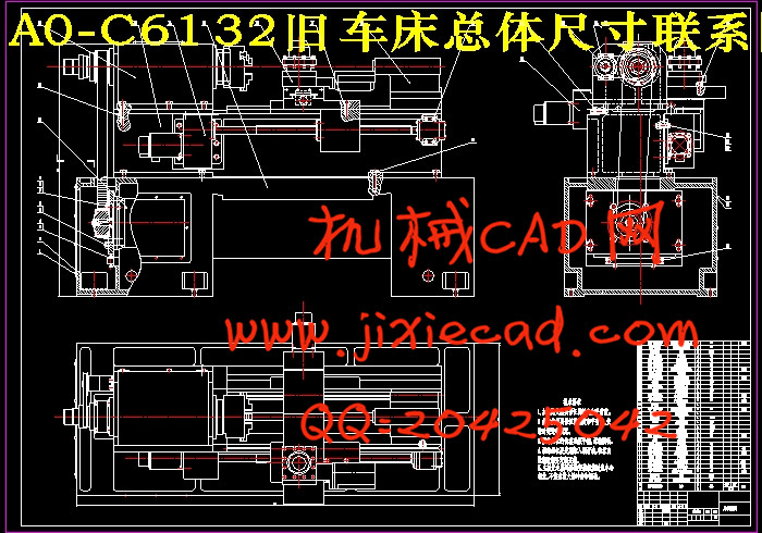
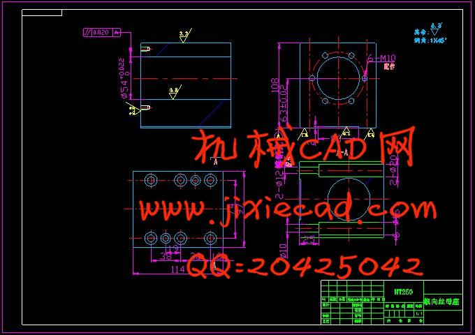
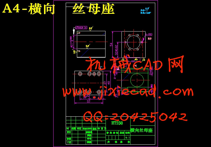
本次设计是对C6132旧机床数控化进给系统的改造的设计。在这里主要包括:主传动系统的设计、纵向进给系统的设计、横向进给系统的设计。而我主要是针对横向进给系统的设计纵向进给系统进行机械设计。这次毕业设计对设计工作的基本技能的训练,提高了分析和解决工程技术问题的能力,并为进行一般机械的设计创造了一定条件。数控设计主要传动系统的机械设计。由于对经济型机床数控化改造的加工精度要求不高,为简化结构、降低成本。通过控制横进给系统,保证设计后的车床具有定位、直线插补、圆弧插补、暂停等功能。为实现机床所要求的传动效率,采用步进电机经联轴器再传动丝杠;为保证一定的传动精度和平稳性,尽量减小摩擦力,选用滚珠丝杠螺母副。
关键词:车床,数控设计, 联轴器,滚珠丝杠
Abstract
This design is about the common Lathe C6132 transformation of NC. Main tasks are: the transformation of the main transmission system, the transformation of the vertical feeding system, horizontal feed system reform. While I was mainly aim at the lateral feeding system mechanical transformation. The graduation project on the design of the basic skills training has improved the analysis and the ability to solve engineering problems, and create a certain condition for general mechanical design.NC transformation is mainly a transformation of mechanical drive system. Because of the economy less precision CNC machining, it is order to simplify the structure and reduce costs. By controlling the cross-feed system, it ensures the modified lathe with positioning, linear interpolation, circular interpolation, and pause. Required for the realization of the transmission efficiency of machine tool, we should us a stepping motor drive and then screw through the coupling. To ensure a certain degree of driving accuracy and stability and minimize friction, a ball screw pair is needed.
Keywords: lathe, NC Transformation , Coupling ,Ball Screw
目 录
摘 要 IIAbstract III
目 录 IV
第1章 概述 1
1.1机床数控化改造及其特点 1
1.2 机床数控化改造的经济分析 2
1.2 机床数控化改造的工艺范围及加工精度 2
1.4 机床数控化改造的发展趋势 3
第2章 机床数控化改造总体方案的制订及比较 5
2.1 总体方案比较与确定 5
2.1主轴系统的方案确定 5
2.2安装电动卡盘 5
2.3换装自动回转刀架 6
2.4螺纹编码器的安装方案 6
2.5进给系统的与设计方案 6
2.6 尾座与设计方案 7
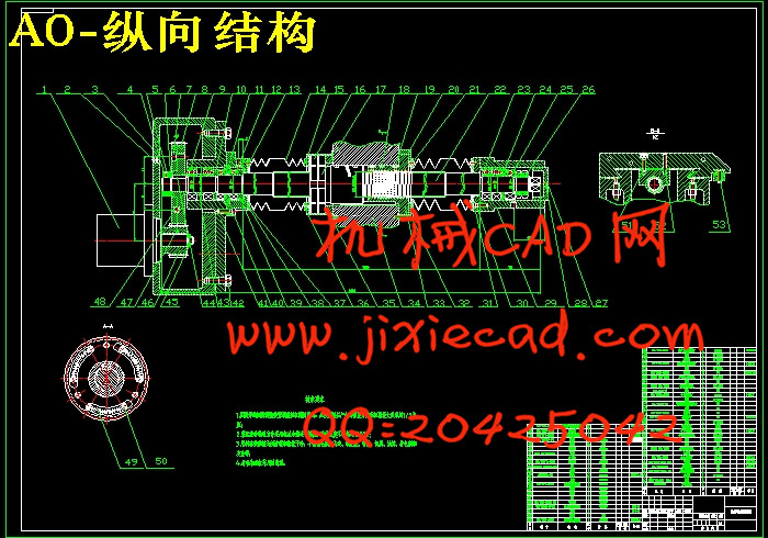
第3章 纵向进给伺服进给结构设计 8
3.1 确定脉冲当量 8
3.2 切削力的计算 8
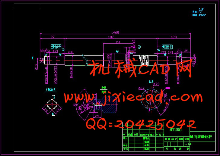
3.3滚珠丝杠螺母副的计算和选型 9
3.3.1 精度的选择 10
3.3.2丝杠导程的确定 10
3.3.3 最大工作载荷的计算 10
3.3.4 最大动载荷的计算 11
3.3.5 滚珠丝杠螺母副的选型 11
3.3.6 滚珠丝杠副的支承方式 12
3.4.3 传动效率的计算 12
3.3.8 刚度的验算 12
3.3.9 稳定性校核 13
3.3.10 临界转速的验证 14
3.4 齿轮传动的计算 15
3.5 步进电动机的选择 15
3.6导轨的特点 17
4.3 导轨的设计 19
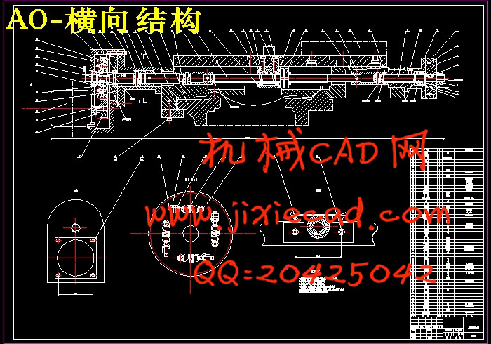
第4章 横向进给伺服进给结构设计 22
4.1切削力的计算 22
4.2 滚珠丝杠螺母副的计算和选型 22
4.2.1 最大工作载荷的计算 22
4.2.2 最大动载荷的计算 22
4.2.3滚珠丝杠螺母副的选型 23
4.2.4 滚珠丝杠副的支承方式 23
4.2.5 传动效率的计算 23
4.2.6 刚度的验算 24
4.2.7 稳定性校核 24
4.2.8临界转速的验证 25
4.3 进给伺服系统传动计算 25
4.3.1确定传动比 25
4.3.2齿轮参数的计算 25
4.4.步进电机的计算和选用 26
4.4.1转动惯量的计算 26
4.4.2电机力矩的计算 27
4.5步进电机的选择 29
结论 31
参考文献 32
致谢 34