设计简介
摘 要
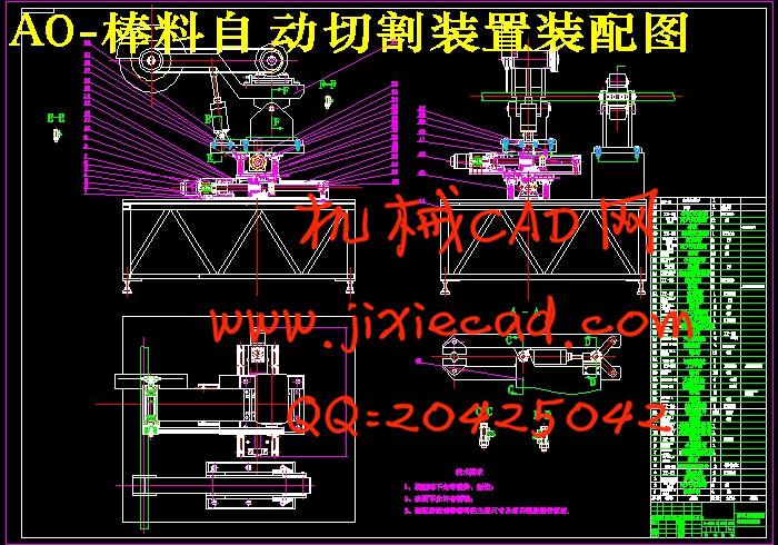
本次设计是对棒料自动切割装配装置的设计。在这里主要包括:传动系统的设计、装夹部位系统的设计、切割片主轴部位系统的设计这次毕业设计对设计工作的基本技能的训练,提高了分析和解决工程技术问题的能力,并为进行一般机械的设计创造了一定条件。整机结构主要由电动机产生动力通过联轴器将需要的动力传递到丝杆上,丝杆带动丝杆螺母,从而带动整机运动,提高劳动生产率和生产自动化水平。更显示其优越性,有着广阔的发展前途。本论文研究内容:
(1) 棒料自动切割装配装置总体结构设计。
(2) 棒料自动切割装配装置工作性能分析。
(3)电动机的选择。
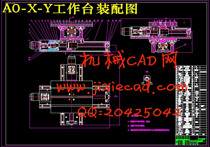
(4) 棒料自动切割装配装置的传动系统、执行部件及机架设计。
(5)对设计零件进行设计计算分析和校核。
(6)绘制整机装配图及重要部件装配图和设计零件的零件图。
关键词:棒料自动切割装配装置; 联轴器;滚珠丝杠
Abstract
This design is the design of assembly of rod material automatic cutting device. Here mainly include: design, drive system design of the cutting blade clamping spindle parts of system design, part of the system of graduation design on the design of the basic skills training, enhancing the analysis and to solve engineering problems, and create a certain condition for general mechanical design.The structure is mainly produced by the motor power through the coupling will need to transfer the power to the screw rod, the screw rod drives the screw rod nut, thereby driving the movement, improve labor productivity and automation level of production. But also show its superiority, there are broad prospects for the development.
The research of this thesis:
(1) the overall structure design of automatic assembly device for cutting bar.
(2) analysis of assembly device performance of rod material automatic cutting.
(3) the choice of motor.
(4) transmission system, execution unit and frame design of automatic assembly device for cutting bar.
(5) the design of components for the design calculation and check.
(6) to draw the assembly drawing and parts assembly diagram and parts diagram design.
Keywords: automatic cutting assembly device;bar coupling;ball screw
目 录
摘 要 IIAbstract III
目 录 IV
1引言 1
1.1棒料自动切割机的研究目的及意义 1
1.1.1棒料自动切割机背景 1
1.1.2意义 1
1.2研究现状及发展趋势 1
1.3本课题研究的内容及方法 2
1.3.1主要的研究内容 2
1.3.2设计要求 2
1.3.3关键的技术问题 3
2 棒料自动切割装配装置总体结构设计 4
2.1设计的要求与数据 4
2.2 同步带传动计算 5
2.2.1 同步带计算选型 5
2.2.2 同步带的主要参数(结构部分) 8
2.2.3 同步带的设计 10
2.2.4 同步带轮的设计 10
2.3 夹紧装置设计 11
3 X结构及传动设计 13
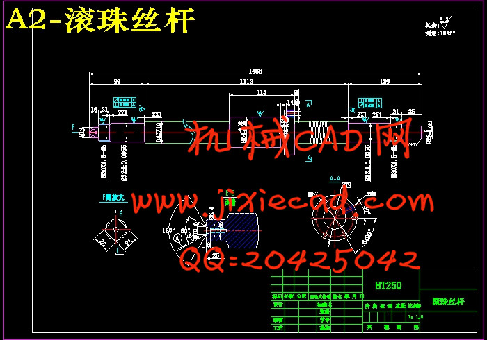
3.1 X向滚珠丝杆副的选择 14
3.1.1导程确定 14
3.1.2确定丝杆的等效转速 14
3.1.3估计工作台质量及负重 14
3.1.4确定丝杆的等效负载 14
3.1.5确定丝杆所受的最大动载荷 15
3.1.6精度的选择 16
3.1.7选择滚珠丝杆型号 16
3.2校核 17
3.2.1 临界压缩负荷验证 17
3.2.2临界转速验证 18
3.2.3丝杆拉压振动与扭转振动的固有频率 19
3.3电机的选择 19
3.3.1电机轴的转动惯量 20
3.3.2电机扭矩计算 21
4 Y向结构设计 23
4.1 Y轴滚动导轨副的计算、选择 23
4.2 滚珠丝杠计算、选择 24
4.3 步进电机惯性负载的计算 27
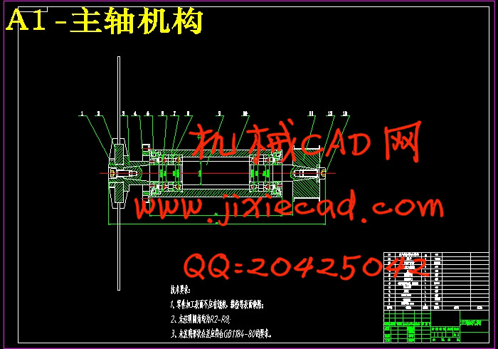
5 主轴组件要求与设计计算 30
5.1 主轴的基本要求 30
5.1.1 旋转精度 30
5.1.2 刚度 30
5.1.3 抗振性 31
5.1.4 温升和热变形 31
5.1.5 耐磨性 32
5.2 主轴组件的布局 32
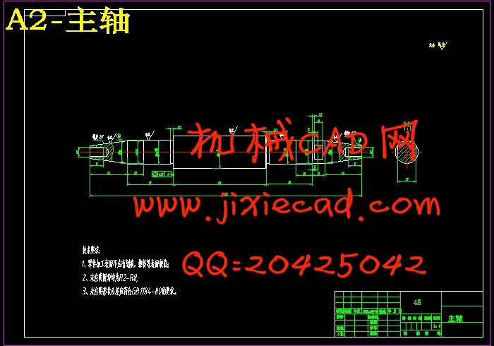
5.3 主轴结构的初步拟定 35
5.4 主轴的材料与热处理 35
5.5 主轴的技术要求 36
5.6 主轴直径的选择 37
5.7 主轴前后轴承的选择 37
5.8 轴承的选型及校核 38
5.9 主轴前端悬伸量 41
5.10 主轴支承跨距 41
5.11 主轴结构图 42
5.12 主轴的校核 42
5.13 轴承寿命校核 45
5.14 主轴组件的润滑和密封 46
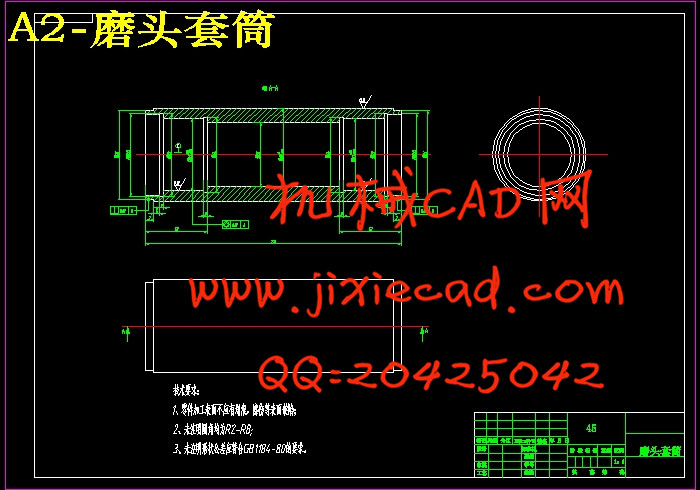
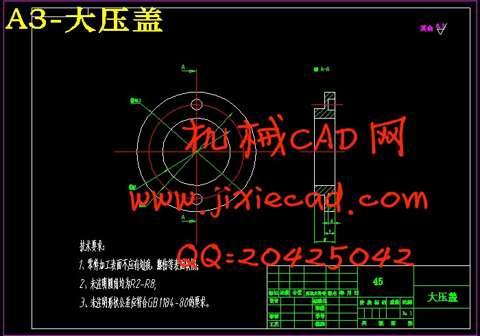
5.15主轴组件中相关部件 47
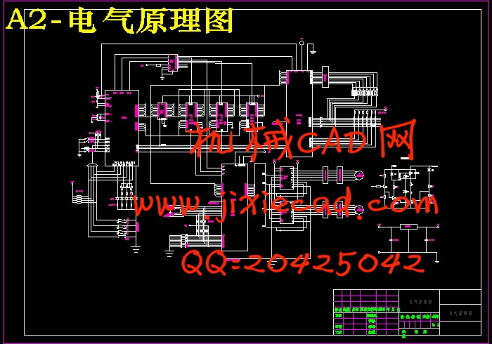
6 硬件电路设计 50
6.1 计算机系统 50
6.2 单片微机数控系统硬件电路设计内容 50
6.3 各类芯片简介 51
6.3.1 8031芯片简介 51
6.3.2 373芯片简介 52
6.3.3 6264芯片简介 52
6.3.4 2764芯片简介 52
6.3.5 8155芯片简介 52
6.3.6 8255芯片简介 53
6.4 存储器扩展电路设计 53
6.4.1 程序存储器ROM的扩展 53
6.4.2 数据存储器RAM的扩展 53
6.4.3 译码电路的设计 54
6.5 I/O接口电路的设计 54
6.5.1 8155通用可编程接口芯片 54
6.5.2 8255可编程接口芯片 55
6.5.3 键盘显示接口电路 55
6.6 8031的时钟电路 56
6.7 复位电路 56
6.8 越界报警电路 57
6.9 掉电保护电路 57
6.10 控制系统的功能 57
6.11 控制工作原理 57
结论 59
参考文献 60
致 谢 61