设计简介
400方车铣转复合滑枕设计
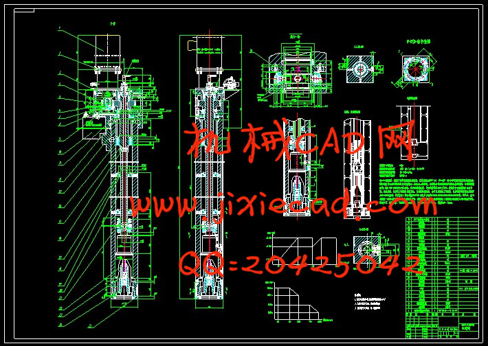
本设计首先将要介绍车铣转复合加工机床国内外研究现状、发展趋势及研制中的关键技术,以及对复合滑枕进行原理设计及结构设计;确定主要结构的技术参数,对结构中的关键部分---丝杠进行设计计算,并进行验算校核,以保证其工作可靠性。
关键词 :复合加工技术;滑枕;液压控制系统;结构
The Design Of 400 milling composite ram
摘 要
随着经济建设的飞速发展,我国的工业需求正逐渐加大,世界上越来越多的复杂零件需要采用复合加工技术进行综合加工,滑枕是车铣转复合机床中非常关键的部件,它带动刀具移动,并给镗、钻、铣功能提供作业动力。滑枕的结构和使用性能关系到机床的使用性能。此次设计对400方车铣转复合滑枕进行了详细说明和计算。设计的滑枕能够满足使用功能的要求,又解决了在起动及制动时的平稳性问题,能够适用于许多工程建设,具有很强的现实意义。本设计首先将要介绍车铣转复合加工机床国内外研究现状、发展趋势及研制中的关键技术,以及对复合滑枕进行原理设计及结构设计;确定主要结构的技术参数,对结构中的关键部分---丝杠进行设计计算,并进行验算校核,以保证其工作可靠性。
关键词 :复合加工技术;滑枕;液压控制系统;结构
The Design Of 400 milling composite ram
Abstract
As the increasing development of the economic construction, our countries’ industrial demand is rising. Complex parts industry needs more and more of the world’s need for comprehensive. Ram is part composite machine tool is the key,it drives the cutter to move, and boring, drilling,milling function provides the power.The structure of ram and the use of performance relate to the use of machine performance.The design of the 400 milling composite ram in detail and calculation.The slippery pillow design to meet the functional requirements,but also solve the stability problem in starting and braking,can use many engineering construction,has the very strong practical significance.The first design will be the introduction of key technology research status,turn milling compound machine tool development trend at home and abroad and development, as well as the principle of design;determined the technical parameters main structure,the structure of the key part and the lead screw carries on the design and checking calculation,in order to ensure the reliability.
Key words:Composite processing technology; Ram; Hydraulic control system; structure
目录
摘 要 I
Abstract II
第1章 绪论 1
1.1车铣转复合加工机床 1
1.2车铣转复合加工机床的优点 1
1. 3国内外现状 2
1.4本课题主要研究内容 3
第2章 400方车铣转复合滑枕总体设计 4
2.1 设计参数 4
2.2 电机的选择 4
第3章 400方车铣转复合滑枕机械结构设计 6
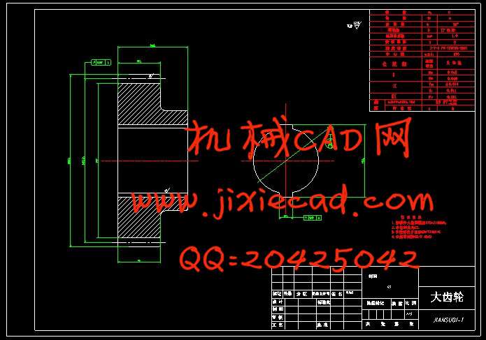
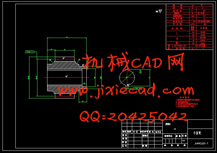
3.1选择齿轮材料及精度等级 6
3.2按齿面接触疲劳强度设计 6
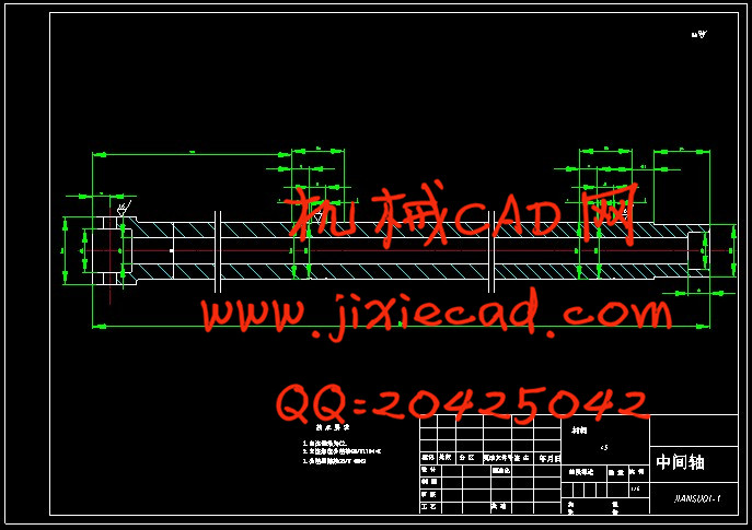
3.3轴类零件的设计 10
3.3.1选择轴的材料 10
3.3.2初算轴径 10
3.4校核轴和轴承 10
3.6键的设计与校核 13
3.7 主轴组件要求与设计计算 13
3.7.1主轴的基本要求 13
3.7.2 主轴组件的布局 15
3.7.3主轴结构的初步拟定 18
3.7.4主轴的材料与热处理 18
3.7.5主轴的技术要求 19
3.7.6主轴直径的选择 19
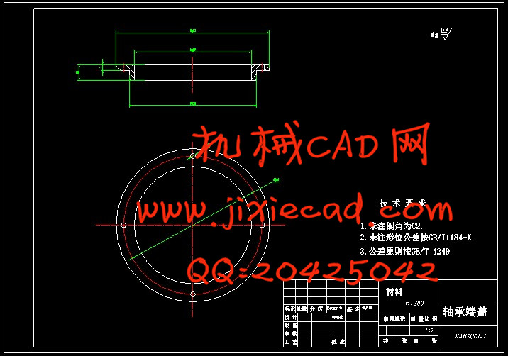
3.7.7主轴前后轴承的选择 20
3.7.8轴承的选型及校核 20
3.7.9主轴前端悬伸量 22
3.7.10主轴支承跨距 23
3.7.11主轴组件的验算 23
3.7.12主轴轴承的润滑 26
3.7.13主轴组件的密封 26
3.7.14轴肩挡圈 27
3.7.15挠度、转角、锁紧力的计算及校核 27
第4章 液压系统原理及设计计算 29
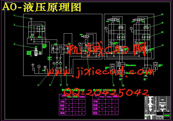
4.1 液压原理 29
4.2 铣头锥柄卡紧放松油缸的主要参数 30
4.3 铣头拉钉卡紧放松油缸的主要结参数 30
4.4活塞杆强度计算 31
4.5 液压缸活塞的推力及拉力计算 32
4.5.1铣头锥柄卡紧放松油缸 32
4.5.2 铣头拉钉卡紧放松油缸 33
4.6 活塞杆最大容许行程 33
4.7 液压缸内径及壁厚的确定 34
4.8 液压系统设计 35
4.8.1系统液压可以完成的工作循环 36
4.8.2 液压执行元件的配置 36
4.8.3 负载分析计算 36
4.8.4 液压泵及其驱动电动机的选择 37
4.8.5其他液压元件的选择 40
4.8.6 液压系统压力损失验算 43
结论 44
致 谢 45
参考文献 46