设计简介
摘 要
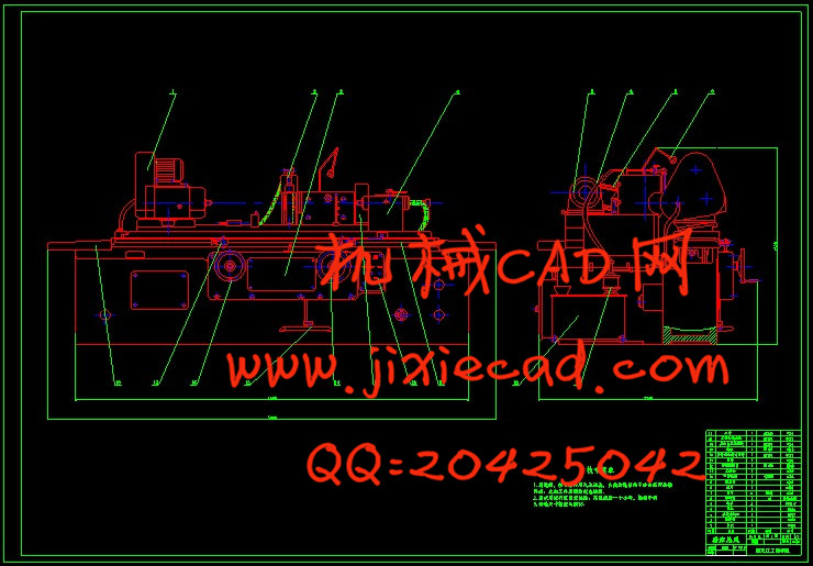
磨床是应用于零件精加工,尤其是淬硬钢件和高硬度特殊材料精加工的一种机床。近年来由于科学技术的发展,现代机械零件的精度和表面粗糙度要求越来越高,各种硬度材料日益增多,所以磨床的应用越来越广泛。
基于市场对外圆磨床的变速要求高,磨削外圆直径大的要求,经过重新布局和对主轴箱的设计后,M1432A型外圆磨床的加工性能得到了很大的提高,外形更加美观,结构更紧凑,操纵也更方便,更省力。主轴可获得6种转速,磨削直径也增加到了320毫米。这些改变都给操纵工人和维修人员带来方便,基本达到了以人为本的目的。
关键词:外圆磨床;淬硬钢件;磨削精度;精加工;粗糙度
ABSTRACT
Grinder is a machine which is widely used in finish processing of the part , especially for the hard steel and the finish machining of the high rigidity special materials. In recent years, with the development of the technology, the need for machine’s precision and surface roughness is getting higher and higher. At the same time, the high rigidity materials are manifold, so the grinder machine is used more widely now.
Based on the high demand for cylindrical grinder and the bigger diameter of the grind circularity, the performance of M1432A cylindrical grinder has gained a prodigious improvement after renewing the layout and designing the headstock. The machine now has the features of perfect, compact, convenient and labor saving. The principal axle can provide six rotation speeds, and the diameter has also increased to 320 millimeter. All of these changes has brought more and more convenient for the manipulators and the maintaining workers. So the changes have achieved the goal of center on human.
Key words: Cylindrical Grinder; Quenched Steel; Grinding Precision; Finish Machining; Roughness
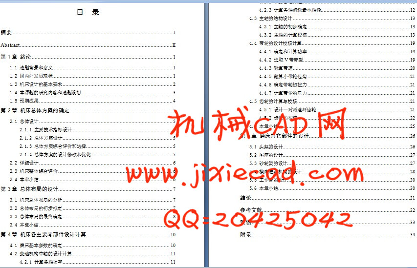
目 录
摘要 I
Abstract II
第1章 绪论 1
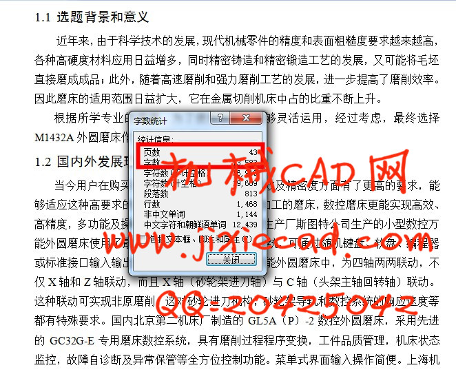
1.1 选题背景和意义 1
1.2 国内外发展现状 1
1.3 机床设计的基本要求 2
1.4 本课题的研究内容和选题设想 3
1.5 预期成果 4
第2章 机床总体方案的确定 5
2.1 总体设计 5
2.1.1 主要技术指标设计 5
2.1.2 总体方案设计 5
2.1.3 总体方案综合评价和选择 5
2.1.4 总体方案的设计修改和优化 5
2.2 详细设计 6
2.3 机床整体综合评价 6
2.4 本章小结 6
第3章 总体布局的设计 7
3.1 机床总体布局的分析 7
3.2 总体布局的初步拟定 7
3.3 总体布局的最终确定 8
3.4 本章小结 9
第4章 机床各主要零部件设计计算 10
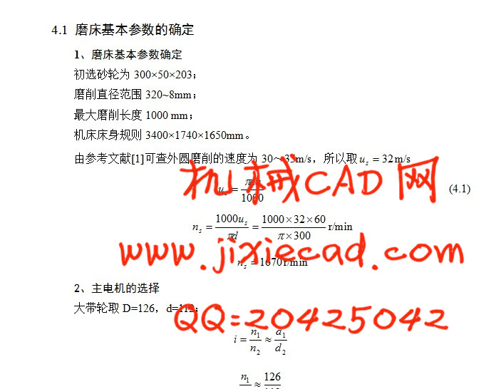
4.1 磨床基本参数的确定 10
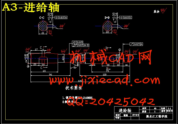
4.2 变速机构中轴的设计计算 11
4.2.1 计算各轴功率 11
4.2.2 计算各轴转速 12
4.2.3 计算各轴初选最小轴径 12
4.3 主轴的结构设计 13
4.3.1 主轴的初步确定 13
4.3.2 主轴的计算校核 13
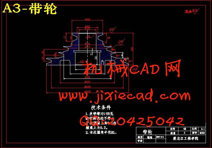
4.4 带轮的设计校核计算 19
4.4.1 确定和计算功率 19
4.4.2 选取V带带型 19
4.4.3 验算带速 20
4.4.5 验算小带轮包角 21
4.4.6 确定带轮初拉力 21
4.4.7 计算带轮的压力 21
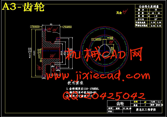
4.5 齿轮的计算与校核 21
4.5.1 设计一对两连环齿轮 21
4.5.2 齿轮的校核 22
4.6 本章小结 25
第5章 磨床其它部件的设计 26
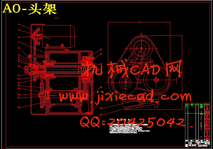
5.1 头架的设计 26
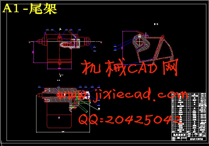
5.2 尾座的设计 27
5.3 砂轮架的设计 27
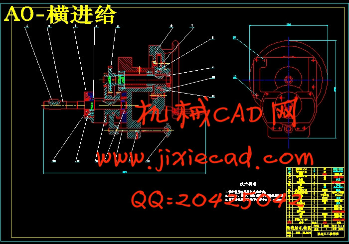
5.4 横向进给机构的设计 28
5.5 工作台的设计 30
5.6 本章小结 30
结论 31
参考文献 32
致谢 33
附录 34