设计简介
摘 要
随着行驶车速的增高,汽车行驶安全性日益重要,汽车制动性直接影响到汽车行驶安全性。本次设计轻型商用车为设计对象,设计高性能、安全性能好的制动系统以满足汽车发展的需求。因而,作为能保证汽车安全行驶的组成部分之一的制动系,需要设计出满足使用性能及安全保障的制动系统。
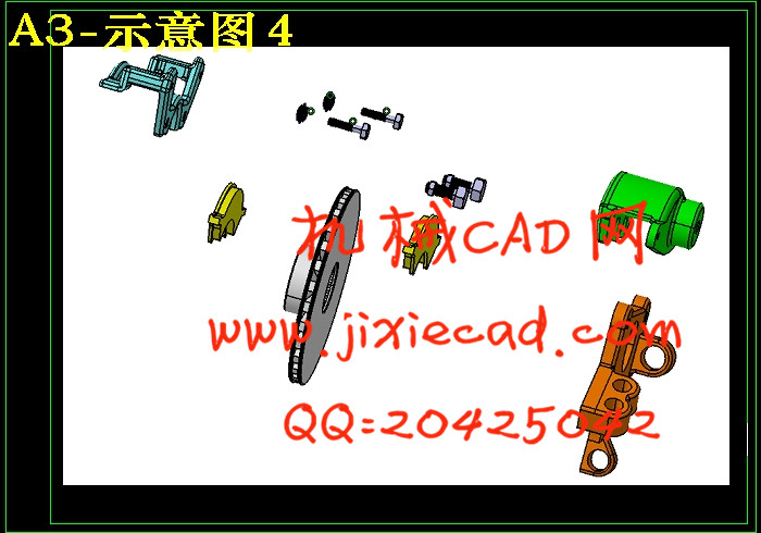
本文系统详细的介绍了汽车制动系的结构型式及其主要构件的设计计算,阐述了制动器的两种结构型式及选择和各自的工作原理、制动系的主要参数及其选择、制动器主要零部件的结构设计和分析计算、制动驱动结构的结构型式选择与设计计算、制动力分配的调节装置等。其中重点介绍了汽车车制动系的主要构件——浮钳盘式制动器、领丛蹄式制动器的分析计算。在绘制二维AUTOCAD图纸的基础上,为更形象表达制动器的结构,还运用CATIA绘图软件,绘制了三维图形和爆炸图。
关键词:行车制动;驻车制动;鼓式制动器;盘式制动器;液压驱动;设计;计算
ABSTRACT
This design specifications is prototypes for Light commercial of CA 1050.Design high performance, safety performance 's breaking system to meet the development of the car. Therefore, as guaranteeing one of the components that the automobile goes safety--the break system, it is necessary to carry on exhaustive designing calculation an theory analysis for composition component.This text mainly introduces the structure pattern of the brake system and its designing calculation of main departments, and explains two kinds of structure patterns and choosing and one's own operation principle of the brake , main parameter of the brake system in the department and choosing, structural design and calculation of the main spare part of the brake , applying the brake urges the structure pattern of the structure to choose and design and calculate , makes the regulation device that power distributes . Especially, it introduces the main member of the department of the brake system among them --Float pincers records of type brake ,Bring plexus hoof type brake's analysis and calculation. In rendering based on two-dimensional AUTOCAD drawing, for the more image express break structure, I still using CATIA drawing software, to draw a 3d graphics and explosion figure.
Key words: Crane Brake;Parking brake;Drum brake;Disc brakes;Hydraulic drive;Design;Calculation
目 录
摘要 IABSTRACT II
第1章 绪 论 1
1.1 制动系统设计的意义 1
1.2 制动系统研究现状 1
1.3 课题设计方法及应解决的主要问题 3
第2章 制动系统总体方案分析和选择 4
2.1 制动能源的选择 5
2.2 驻车制动系 6
2.3 行车制动系 6
2.4 液压分路系统的形式的选择 6
2.4.1 II型回路 7
2.4.2 X型回路 7
2.4.3 其他类型回路 7
2.5 制动原理和工作过程 8
2.5.1 鼓式制动器制动原理和过程 8
2.5.2 盘式制动器制动原理和过程 8
2.6 制动器的形式方案分析 9
2.6.1鼓式制动器 9
2.6.2 盘式制动器 10
2.7 本章小结 11
第3章 制动系主要参数确定 12
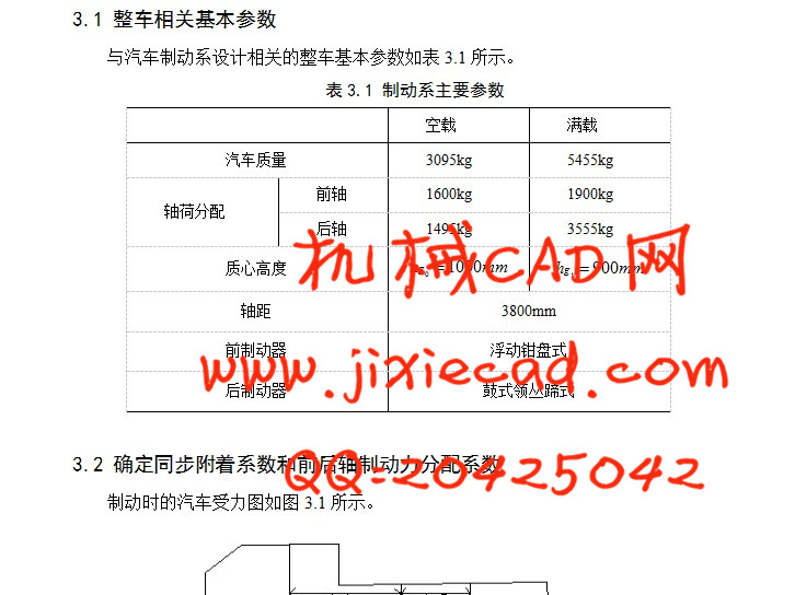
3.1 整车相关基本参数 12
3.2 确定同步附着系数和前后轴制动力分配系数 12
3.3 制动器最大制动力矩确定 14
3.4 鼓式制动器的主要参数选择 14
3.4.1 制动鼓直径D 15
3.4.2 摩擦衬片宽度b和包角β 15
3.4.3 制动器中心到张开力作用线和距离 16
3.4.4 制动蹄支销中心的坐标位置是k与c 16
3.4.5 摩擦片摩擦系数 16
3.5 盘式制动器的主要参数选择 16
3.5.1 制动盘直径D 16
3.5.2 制动盘厚度 16
3.5.3 摩擦衬块外半径和内半径 17
3.5.4 摩擦衬块工作面积 17
3.6 本章小结 17
第4章 制动器的设计与计算 18
4.1制动器摩擦面的压力分布规律 18
4.2 单个制动器制动力矩计算 18
4.2.1 鼓式制动器制动力矩计算 18
4.2.2 盘式制动器制动力矩计算 20
4.3 驻车制动的制动力矩计算 21
4.4 制动衬片的耐磨性计算 22
4.5 制动距离的计算 23
4.6 本章小结 24
第5章 液压制动驱动机构的设计计算 25
5.1 制动驱动机构的形式 25
5.2 液压制动驱动机构的设计计算 25
5.2.1 制动轮缸直径d的确定 25
5.2.2 盘式制动器轮缸活塞宽度与缸筒壁厚 26
5.2.3 鼓式制动器轮缸活塞宽度与缸筒壁厚 27
5.2.4 制动主缸的尺寸参数计算 27
5.2.3 制动踏板力FP 31
5.2.4 制动力分配调节装置的选取 32
5.2.5 液压制动软管的计算 33
5.3 真空助力器的设计计算 33
5.4 制动器的主要结构元件 34
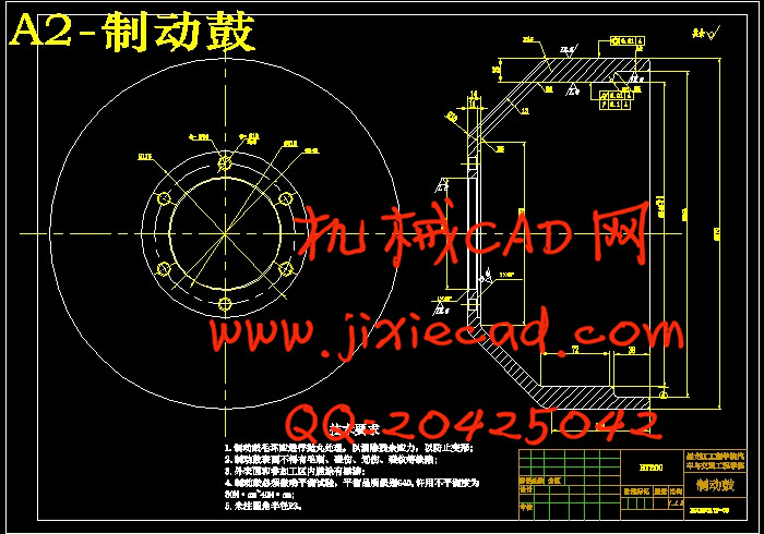
5.4.1 制动鼓 34
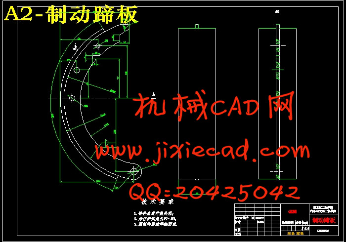
5.4.2 制动蹄 35
5.4.3 摩擦衬(片)块 35
5.4.4 制动底板 36
5.4.5 支承 36
5.4.6 制动轮缸 36
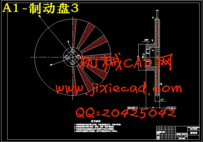
5.4.7 制动盘 37
5.4.8 制动钳 38
5.4.9 制动块 38
5.5 自动间隙调整机构 39
5.6 本章小结 40
结论 41
参考文献 42
致谢 43