设计简介
圆盘给料机传动系统设计
摘要
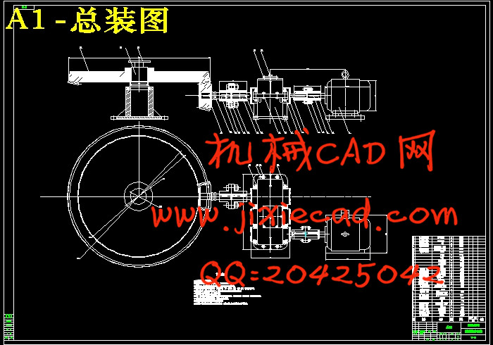
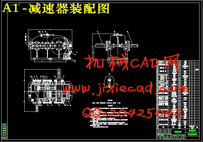
圆盘给料机的传动进给系统是圆盘给料机的重要组成部分,对圆盘给料机整体的功能有着决定性的作用,通过传动系统可以是无聊顺利的进入下一道程序。所以,设计圆盘给料机的传动系统是一个很重要的部分,有利于深入了解进给系统的原理和功能,进而探求可能的优化设计。设计了以二级减速器为核心基础,加上两个锥齿轮为基础的传动系统。通过此次的设计,首先进行了进给系统的总体方案设计,选择合适的传动比,并通过计算选择进给系统的其他相关零件;其次对传动系统的刚度、强度等进行了校核验算;然后进行最后的装配成一体的传动系统,从而达到我们所设计的目的。最后利用Auto CAD软件绘制了相关的零件图和装配图。经过圆盘给料机的设计我们更加准确的了解机械设计的知识。
关键词:圆盘给料机,传动系统 ,减速器 ,传动比
The transmission system Of Disc feeder
摘要
圆盘给料机的传动进给系统是圆盘给料机的重要组成部分,对圆盘给料机整体的功能有着决定性的作用,通过传动系统可以是无聊顺利的进入下一道程序。所以,设计圆盘给料机的传动系统是一个很重要的部分,有利于深入了解进给系统的原理和功能,进而探求可能的优化设计。设计了以二级减速器为核心基础,加上两个锥齿轮为基础的传动系统。通过此次的设计,首先进行了进给系统的总体方案设计,选择合适的传动比,并通过计算选择进给系统的其他相关零件;其次对传动系统的刚度、强度等进行了校核验算;然后进行最后的装配成一体的传动系统,从而达到我们所设计的目的。最后利用Auto CAD软件绘制了相关的零件图和装配图。经过圆盘给料机的设计我们更加准确的了解机械设计的知识。
关键词:圆盘给料机,传动系统 ,减速器 ,传动比
The transmission system Of Disc feeder
Abstract
Disk drive into the feeder to the system is an important part of disc feeder to the overall function of the feeder disc has a decisive role, bored through the transmission system can smoothly enter the next program. Therefore, the design of disk drive system of the feeder is a very important part of help-depth understanding of the principle and function of the feed system, and then explore possible to optimize the design. Designed two reducer, coupled with two bevel gears based on the transmission system. Through the design, the first into the overall design to the system, select the appropriate transmission ratio, and by calculating the feed system related parts; followed by the transmission system of stiffness, strength checking; and then proceed to the final assembly into one of the transmission system, so as to achieve the purpose of our design. Finally, we use Auto CAD software to draw the parts and assembly drawings. After the disc feeder design more accurate understanding of the knowledge of mechanical design.
Keywords: Disc feeder ,Transmission ,reduction gear ,ratio of transmission
目录
1绪论 1
1.1 圆盘给料机的概念 1
1.2我国圆盘给料设备的发展与现状 1
1.3 圆盘给料机的工作原理和分类 3
1.4 课题的研究方法,论文构成及研究内容 3
2系统传动方案设计和运动学及动力学参数设计计算 4
2.1系统传动方案设计 4
2.2 系统运动学及动力学参数设计计算 4
2.2.1 选择电动机 4
2.2.2 总传动比并分配传动 6
2.2.3 各轴功率、转速、转矩计算 6
3 传动件设计计算 8
3.1 高速级大、小齿轮的设计计算 8
3.1.1 选择齿轮材料 8
3.1.2 选取设计参数 8
3.1.3 按齿面接触疲劳强度设计 8
3.1.4 齿轮的几何尺寸计算 8
3.1.5 校核弯曲疲劳强度 9
3.1.6 精度设计 9
3.1.7 结构设计 9
3.2低速级大、小齿轮的设计计算 10
3.2.1 选择齿轮材料 10
3.2.2 选取设计参数 10
3.2.3 按齿面接触疲劳强度设计 10
3.2.4 齿轮的几何尺寸计算 11
3.2.5 校核弯曲疲劳强度 11
3.2.6 精度设计 11
3.2.7 结构设计 12
3.2.8 润滑方式 12
4 轴系零件的校核计算 13
4.1Ⅰ轴的设计计算 13
4.1.1 材料的选择及轴颈的确定 13
4.1.2 确定各轴段直径 13
4.1.3 各轴段的长度 14
4.1.4 Ⅰ轴的校核 15
4.1.5 轴承的校核 18
4.1.6 与联轴器的连接轴的键的设计与校核 19
4.2 Ⅱ轴的设计计算 19
4.2.1 轴径的确定 19
4.2.2 各轴段直径的确定 20
4.2.3 各轴段长度的确定 20
4.2.4 Ⅱ轴的校核 21
4.2.5 轴承的校核 24
4.2.6 键的选择与校核 25
4.3 Ⅲ轴的设计 26
4.3.1 轴径的确定 26
4.3.2 各轴段直径的确定 26
4.3.3 各轴段长度的确定 27
4.3.4 第三轴的校核 28
4.3.5 轴承的校核 31
4.3.6 键的选择与校核 32
4.4 联轴器的选择 33
5 锥齿轮的设计 34
5.1选精度等级、材料及齿数 34
5.1.1 精度等级选8级精度 34
5.1.2 初选小齿轮齿数 34
5.2按齿面接触强度设计 34
5.2.1 确定公式内的各计算数值 34
5.2.2 计算 36
5.2.3 按齿根弯曲强度设计 37
5.2.4 几何尺寸的计算 38
6 其他部件的设计 40
6.1润滑设计 40
6.2 密封设计 40
6.3.箱体的设计 41
6.3.1 箱盖顶部外表面轮廓的确定 41
6.3.2齿轮1处的箱盖顶部外表面轮廓的确定 41
6..3.3底座凸缘厚度 41
6..3.4 箱体结构尺寸 42
6.3.5减速器附件的设计 45
7总 结 46
致 谢 47
参考文献 48