设计简介
钢筋弯曲机设计说明书
摘 要
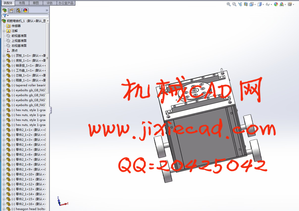
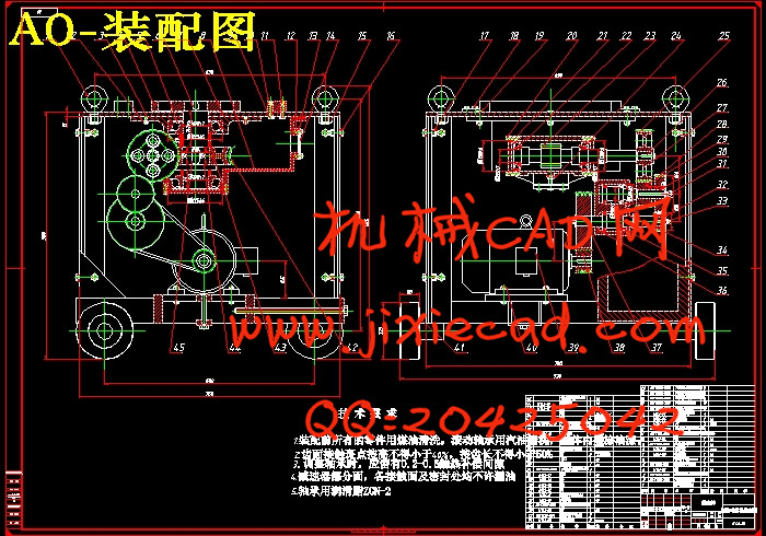
钢筋弯曲机是建筑业常用的工程机械之一,主要用于各种型号的钢筋的弯曲,以用于工程施工工地上。通过强度计算分析,认为现有弯曲机的大部分零件有较大的设计裕量,需要改变个别零部件及电动机功率即可大幅度提高加工能力,满足ф40钢筋的弯曲加工。.本文所设计的半自动可调速钢筋弯曲机适用于弯曲Φ6-Φ40毫米钢筋之用,本机的传动机构采用全封闭式,变速杆换挡,可使工作盘得到两种转速,钢筋的弯曲角度由工作盘侧面的挡块调节,机械部分通过电器控制实现半自动。钢筋弯曲机适用于建筑行业弯曲Φ6—Φ40钢筋之用。 本机工作程序简单,弯曲形状一致,调整简单,操作方便,性能稳定,它能将Q235Φ40圆钢或Φ8—Φ32螺纹钢筋弯曲成工程中所需要的各种形状。
关键词 钢筋弯曲机 ;弯矩 ;主轴扭矩
Abstract
摘 要
钢筋弯曲机是建筑业常用的工程机械之一,主要用于各种型号的钢筋的弯曲,以用于工程施工工地上。通过强度计算分析,认为现有弯曲机的大部分零件有较大的设计裕量,需要改变个别零部件及电动机功率即可大幅度提高加工能力,满足ф40钢筋的弯曲加工。.本文所设计的半自动可调速钢筋弯曲机适用于弯曲Φ6-Φ40毫米钢筋之用,本机的传动机构采用全封闭式,变速杆换挡,可使工作盘得到两种转速,钢筋的弯曲角度由工作盘侧面的挡块调节,机械部分通过电器控制实现半自动。钢筋弯曲机适用于建筑行业弯曲Φ6—Φ40钢筋之用。 本机工作程序简单,弯曲形状一致,调整简单,操作方便,性能稳定,它能将Q235Φ40圆钢或Φ8—Φ32螺纹钢筋弯曲成工程中所需要的各种形状。
关键词 钢筋弯曲机 ;弯矩 ;主轴扭矩
Abstract
Steel bending machine is commonly used in the construction industry, one ofconstructionmachinery, mainly for various types of bending steel bars for construction site. Strengthcalculation through analysis, that the existing bending machine are larger parts of most of the design margin, need to change the individual parts and components and electrical power can significantly increase the processing capacity to meet the needs of the bending of reinforced ф40. Can also be upgraded to steel bending machine. This article is designed to speed steel semi-automatic bending machine for bending Φ6-Φ40 mm steel used, the machine-wide closed-end transmission, gear shift, work can be two types of disk rotational speed, angle of bending steel plate by the side of the block adjustment, the mechanical parts of electrical control through the realization of semi-automatic. -type steel bending machine bending applied to the construction industry reinforced Φ6-Φ40 purposes. Working procedures of this machine is simple, curved shape of the same adjustment is simple, easy to operate, stable performance, it will be round or Q235Φ40 thread Φ8-Φ32 bending steel into works of various forms required for.
Keywords Steel bending machine ;Moment before ;End moment ;Spindle torque
目 录
摘 要 I
Abstract II
第1章 绪 论 2
第2章 弯矩计算与电动机选择 3
2.1 弯矩计算与电动机选择 3
2.2 材料达到屈服极限时的始弯矩 3
第3章 v带传动设计 5
3.1 V带轮的设计计算 5
第4章 圆柱齿轮设计 8
4.1 选择材料 8
4.2 按接触强度进行初步设计 8
4.3 齿轮校核 9
4.4 齿轮及齿轮副精度的检验项目计算 12
第5章 蜗轮蜗杆设计 14
5.1 选择蜗轮蜗杆传动类型 14
5.2 选择材料 14
5.4 校核计算 19
第6章 轴的设计 21
6.1 计算作用在轴上的力 21
6.2 计算支力和弯矩 21
6.3 对截面进行校核 24
第7章 主轴设计 27
7.1 计算作用在轴上的力 27
7.2 计算支力和弯矩 27
7.3 对截面进行校核 29
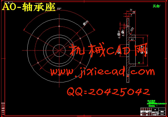
第8章 轴承的选择 31
总 结 32
参考文献 33
致 谢 34