设计简介
用于液滴分析仪的供液系统设计说明书
ABSTRACT
The design of hydraulic drive manipulator movements undertheprovisions of the order , use the basic theory, basic knowledge and related mechanical design expertise comprehensively to complete the esign,and drawing the necessary assembly, hydraulic system map, PLC control system diagram . Manipulator mechanical structure using tanks, screw ,guide tubes and other mechanical device component ;In the hydraulic drive bodies ,manipulator arm stretching using telescopic tank ,rotating column of tanks used rack ,manipulator movements using tank movements ,thecolumn takes the horizontal movement of tanksThis text introduce upper and lower material spend design process of manipulator , it include to whole job requirements and analysis of situation of system mainly, confirm the whole structural design systematic in hydraulic pressure through the working course of the system. Analyse whole cyclical process , confirm systematic operation principle picture , require the hydraulic pressure component of the standard for selection according to systematic parameter, finish theinstallation diagram systematic in hydraulic pressure. Hydraulic pressure integrate piece as now main part , hydraulic pressure of system , hydraulic pressure atpresent integrate pieces of application and development receive domestic and international hydraulic pressure extensive attention of circle, hydraulic pressure integrate research and development of CAD of piece already offer effective support for engineering design of the hydraulic pressure, while design the system integration one of hydraulic pressure of the manipulator, can combine with real processing technology . And CAD integrating one to the present hydraulic pressure has very good understanding.
Keywords: manipulator ,Drive , Hydraulic manifold block , Elements
目录
一、前言------------------------------------------------------------3
1.1设计背景----------------------------------------------------3
1.2 设计意义----------------------------------------------------4
二、产品状况分析-----------------------------------------------4
2.1 现状分析----------------------------------------------------4
2.2 设计定位----------------------------------------------------5
三、设计构思-------------------------------------------------5
3.1 设计初案--------------------------------------------------5
3.2 人机相互分析----------------------------------------------6
3.3 各部分细化设计--------------------------------------------6
四、产品设计过程----------------------------------------------------7
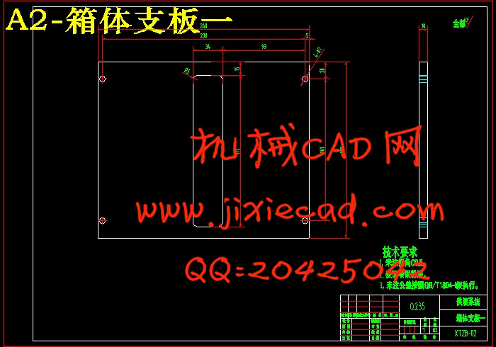
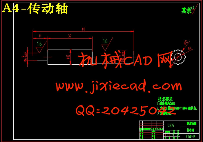
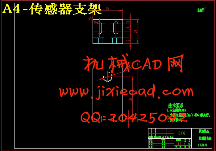
4.1典型零件图-----------------------------------------------------8
4.2 齿轮传动的设计 -----------------------------------------------9
4.3轴强度的校核--------------------------------------------------10
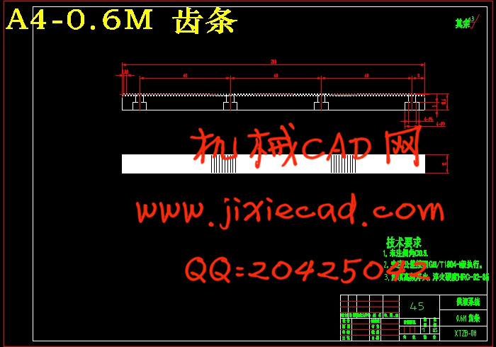
4.4齿轮齿条传动的设计 -------------------------------------------11
4.5步进电机的特点------------------------------------------------12
4.6步进电机的工作原理 -------------------------------------------13
4.7步进电机的计算------------------------------------------------14
设计总结-----------------------------------------------------21
参考文献---------------------------------------------------22
致谢--------------------------------------------------------------23
摘 要
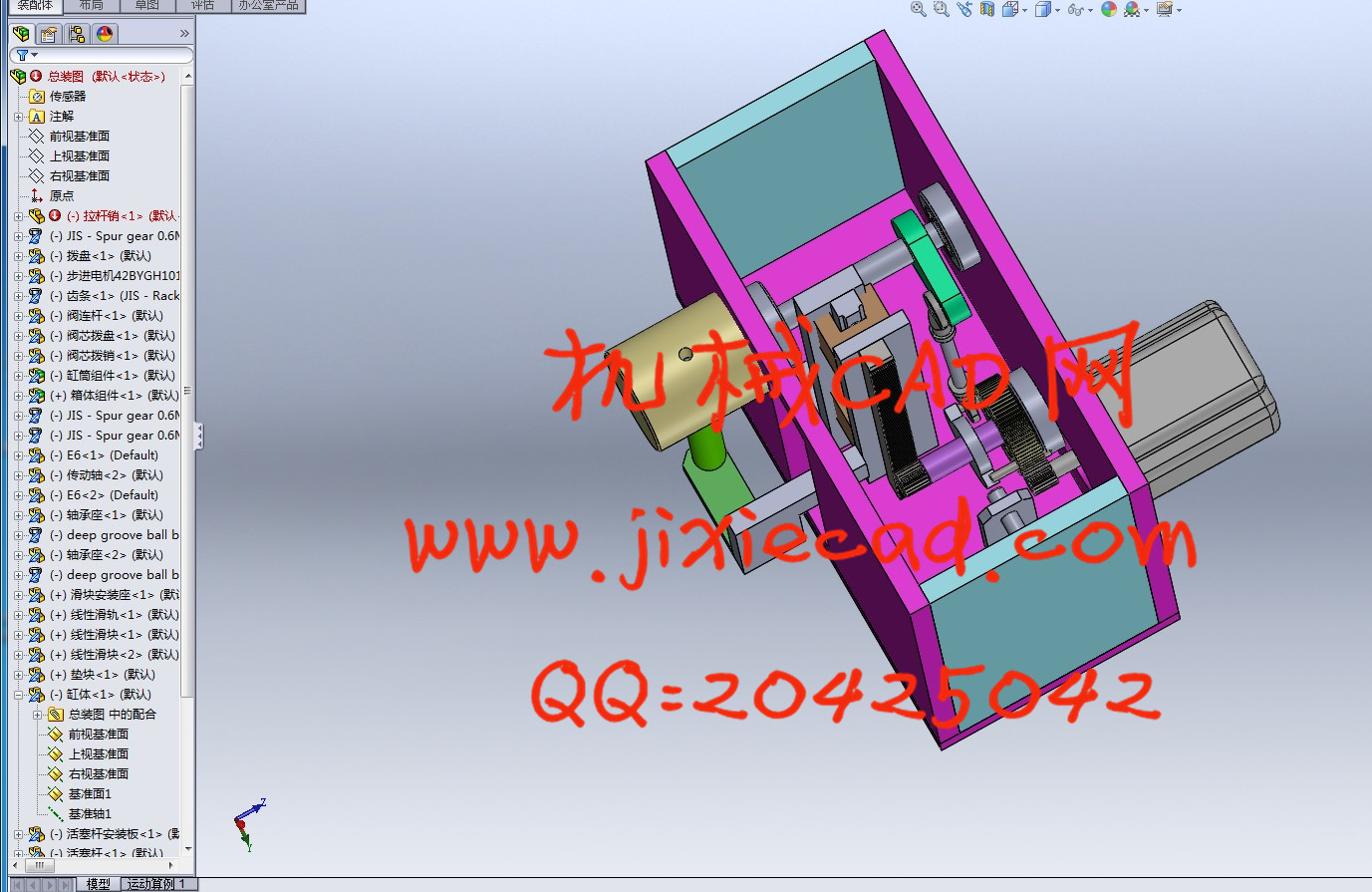
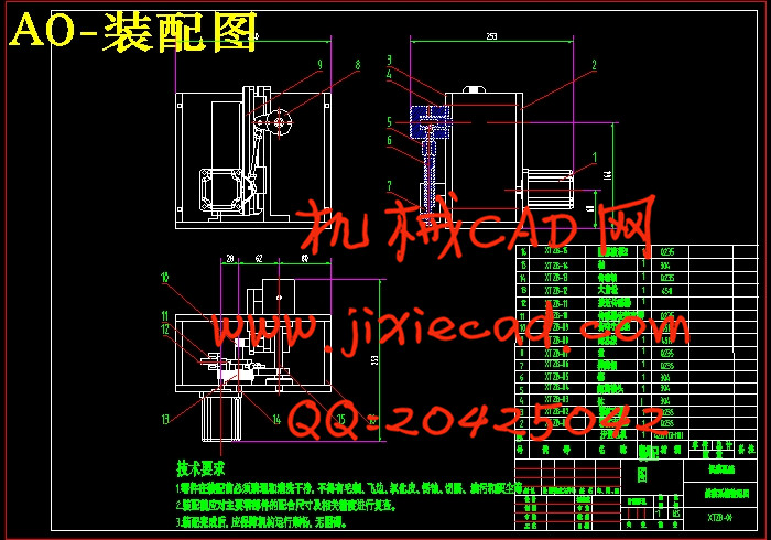
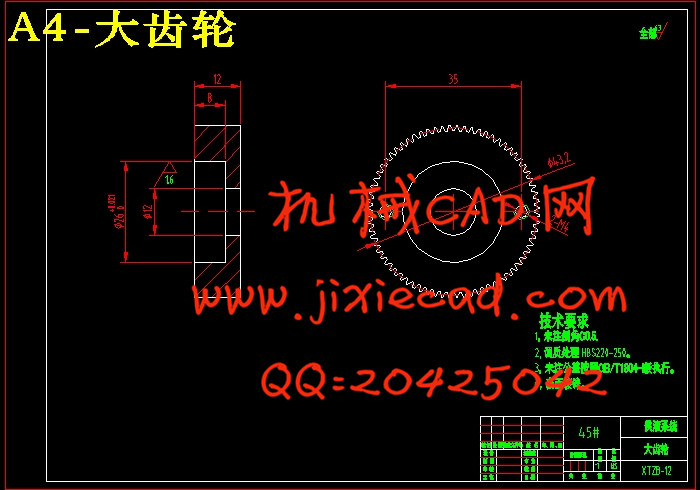
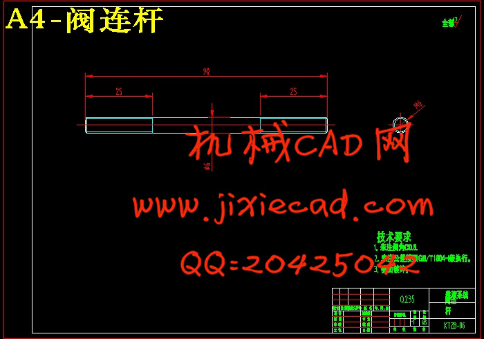
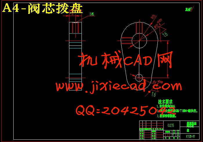
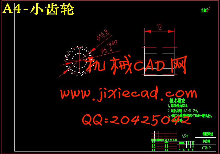
为了保证液滴分析在液滴的准平衡状态下进行 ,提出了一套由计算机软件控制、单步进电机及其细分驱动器驱动的精密微量供液系统 ,它能够提供流量极小且流速稳定的液流。通过特殊设计的机械结构 ,包括阶跃半径拨盘和内置沟槽的连杆等 ,实现一个步进电机在时序上错开分别驱动传动部分和切换阀部分。光电传感器用于解决可能出现的丢步问题。平均值滤波用于剔除测量过程中各种扰动因素对信号造成的高频噪声。本课题由“2007国家自然科学基金项目(60702004)”资助,旨在利用“液滴指纹图”实现液体细微差别的测量识别。液滴分析仪是获得“液滴指纹图”的硬件基础,因此仪器的精度、可靠性、稳定性等性能指标直接影响液体的细微识别成功与否。 从理论上说,液滴分析应该在被测液滴处于静止的平衡状态下进行,这意味着液滴生长速度要慢而且稳定。而液滴生长速度本质上是由供液系统对毛细管流量的定量控制决定的,因此各种液滴分析系统都需要有一个流量极小且流速稳定的供液装置。为了解决上述问题,本文开发了一种性能可靠、精度较高的可实现自动控制的微量供液系统。该系统的研制主要包括机械结构设计以及控制系统软硬件设计两个部分。 在机械设计方面,本文在对国内外计量泵发展状况、技术特点进行研究与分析的基础上,设计了供液系统的机械结构,本系统的传动装置采用活塞计量泵的基本原理,利用步进电机驱动一对减速齿轮,通过传动轴及滑动键带动螺杆在竖直方向上移动。螺杆的运动即可改变活塞的有效行程,进而引起计量泵的流量变化。此外,本文对传动机构的重点零件进行了全面校核,确保了传动机构的可行性和可靠性。 在控制电路硬件设计方面,本文以AT89C52单片机为核心,将恒流斩波细分驱动方案用到了步进电机的驱动系统中,通过功能扩展和接口技术等实现了对供液装置的驱动和控制。此外,本系统可通过标准异步通信协议与PC机进行通信,从而实现了对泵流量的辅助控制以及相关状态信息的处理和显示;在软件程序研发方面,本文在Keil C51平台下完成了主程序和步进电机控制等子程序的开发,与硬件电路配合实现了对系统供液的实时控制。在此基础上,本文分析了单片机系统干扰产生的原因及其影响,并从硬件和软件两方面提出了抗干扰措施。 通过研究证明:本文所设计的基于单片机技术的微量供液系统,能够对供液系统的流量和流速实现精确控制,具有重要的实用价值。本系统可用于诸如液体生产工艺控制、环境监测等需要微量供液的场合,是一种低成本、高灵活的方案。ABSTRACT
The design of hydraulic drive manipulator movements undertheprovisions of the order , use the basic theory, basic knowledge and related mechanical design expertise comprehensively to complete the esign,and drawing the necessary assembly, hydraulic system map, PLC control system diagram . Manipulator mechanical structure using tanks, screw ,guide tubes and other mechanical device component ;In the hydraulic drive bodies ,manipulator arm stretching using telescopic tank ,rotating column of tanks used rack ,manipulator movements using tank movements ,thecolumn takes the horizontal movement of tanksThis text introduce upper and lower material spend design process of manipulator , it include to whole job requirements and analysis of situation of system mainly, confirm the whole structural design systematic in hydraulic pressure through the working course of the system. Analyse whole cyclical process , confirm systematic operation principle picture , require the hydraulic pressure component of the standard for selection according to systematic parameter, finish theinstallation diagram systematic in hydraulic pressure. Hydraulic pressure integrate piece as now main part , hydraulic pressure of system , hydraulic pressure atpresent integrate pieces of application and development receive domestic and international hydraulic pressure extensive attention of circle, hydraulic pressure integrate research and development of CAD of piece already offer effective support for engineering design of the hydraulic pressure, while design the system integration one of hydraulic pressure of the manipulator, can combine with real processing technology . And CAD integrating one to the present hydraulic pressure has very good understanding.
Keywords: manipulator ,Drive , Hydraulic manifold block , Elements
目录
一、前言------------------------------------------------------------3
1.1设计背景----------------------------------------------------3
1.2 设计意义----------------------------------------------------4
二、产品状况分析-----------------------------------------------4
2.1 现状分析----------------------------------------------------4
2.2 设计定位----------------------------------------------------5
三、设计构思-------------------------------------------------5
3.1 设计初案--------------------------------------------------5
3.2 人机相互分析----------------------------------------------6
3.3 各部分细化设计--------------------------------------------6
四、产品设计过程----------------------------------------------------7
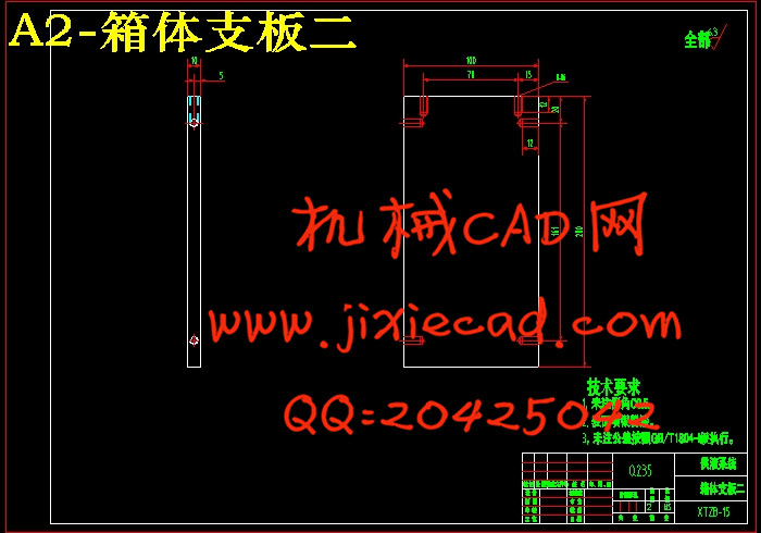
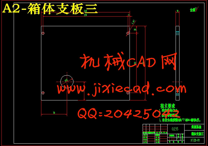
4.1典型零件图-----------------------------------------------------8
4.2 齿轮传动的设计 -----------------------------------------------9
4.3轴强度的校核--------------------------------------------------10
4.4齿轮齿条传动的设计 -------------------------------------------11
4.5步进电机的特点------------------------------------------------12
4.6步进电机的工作原理 -------------------------------------------13
4.7步进电机的计算------------------------------------------------14
设计总结-----------------------------------------------------21
参考文献---------------------------------------------------22
致谢--------------------------------------------------------------23