设计简介
摘 要
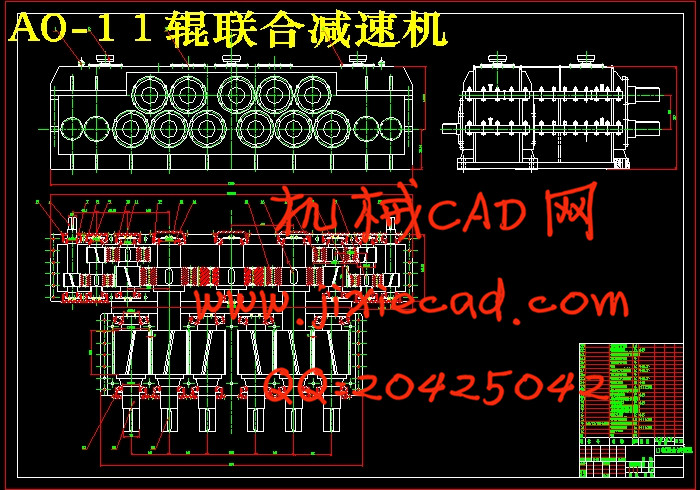
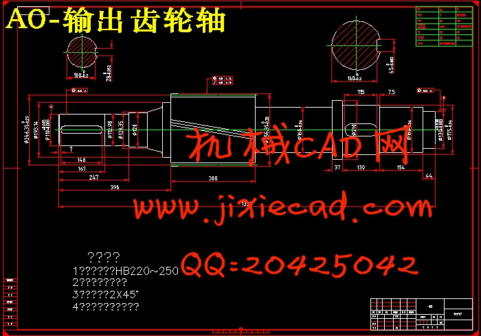
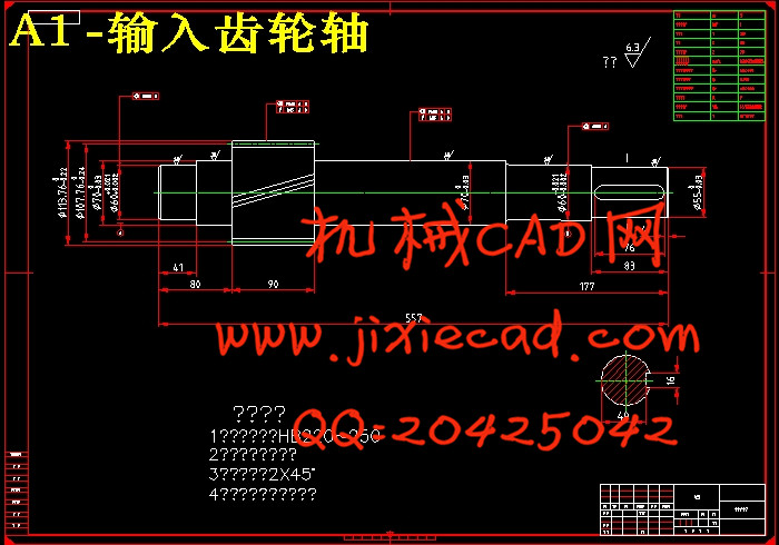
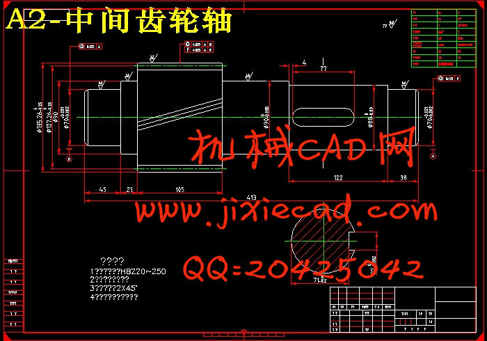
本文从研究矫直管机理入手,设计了一台11辊矫直机用的联合齿轮箱,并对联合齿轮箱进行结构设计,包括联合齿轮箱的传动比计算、各齿轮的参数计算、各传动轴的设计与校核计算。并完成总装图的绘制及零件图的绘制,并用机械制图软件绘制。在结构设计阶段,应牢固树立保证各级齿轮啮合良好的意识,采用适当的焊接箱体结构和轴系结构,合理确定轮齿旋向和齿轮旋转方向,重视润滑配管设计,以保证设计计算落到实处,减速机工艺性好,使用方便、可靠。
本课题主要是针对矫直机上的联合减速机进行设计。
关键词 矫直机、联合齿轮箱、传动轴
ABSTRACT
This paper starts from the study of the governing mechanism, combined gear box with a 11 roller straightening machine straightening the design, and structure design of the combined gear box, calculation, calculation, design and checking calculation of parameters of each gear of the transmission shaft of the transmission gear box comprises a joint. And complete the drawing and parts drawing assembly diagram, and mechanical drawing software rendering.
In the stage of structural design, should firmly establish the assurance levels of gear meshing good sense, welded body structure and the shafting structure suitable, reasonably determine the gear rotation direction and rotation direction of attention gear, lubrication piping design, to ensure that the design and calculation of implement, deceleration machine art is good, easy to use, reliable.
This topic is mainly combined speed reducer for straightening machine of design.
Key words Straightening machine, gear box, transmission shaft
目 录
摘 要 IIn the stage of structural design, should firmly establish the assurance levels of gear meshing good sense, welded body structure and the shafting structure suitable, reasonably determine the gear rotation direction and rotation direction of attention gear, lubrication piping design, to ensure that the design and calculation of implement, deceleration machine art is good, easy to use, reliable.
This topic is mainly combined speed reducer for straightening machine of design.
Key words Straightening machine, gear box, transmission shaft
目 录
ABSTRACT II
1 绪 论 1
1.1 本课题研究目的与意义 1
1.2 本课题国内外发展概况 1
1.3 矫直机的发展趋势 1
2 系统总体方案的确定 3
2.1 设计思想 3
2.2 初选电机减速器系统方案 3
2.3 输送处传动系统的确定 4
2.4 系统总体方案的确定 4
3 电动机的选择 6
3.1 电动机类型选择 6
3.2 电动机功率的选择 6
3.4 确定电动机型号 6
4 V带的设计计算 7
4.1 传动比的分配 7
4.2 各轴的转速、功率和转矩 7
4.3 带传动方案的确定 8
4.4 带传动设计计算 8
4.5 带轮的结构设计 10
5 减速器的设计 12
5.1 齿轮的设计 12
5.1.1 高速级齿轮设计计算: 12
5.1.2 低速级齿轮设计计算 16
5.2 轴的设计计算 20
5.2.1 低速轴(轴3)的设计计算 20
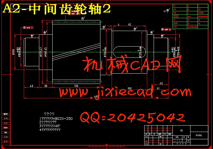
5.2.2 中间(轴2)轴的设计计算 22
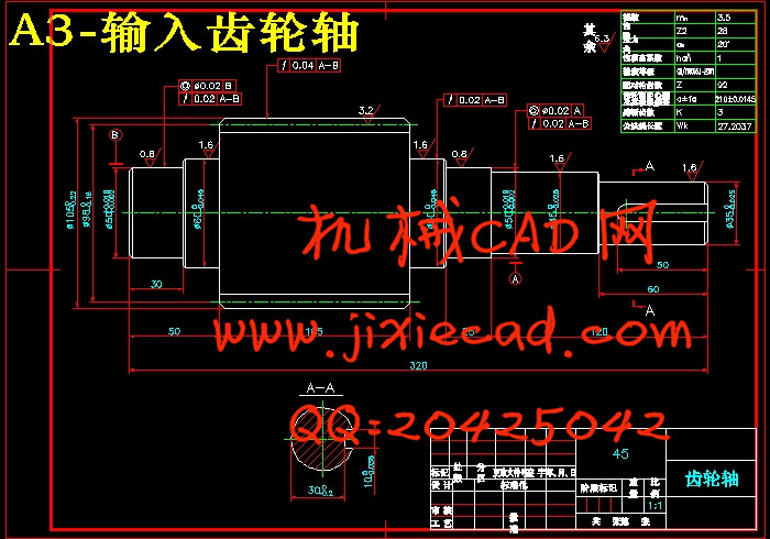
5.2.3 输入轴(轴1)的设计计算 23
5.3 轴的校核 24
5.3.1 输出轴(轴3)的校核 24
5.3.2 中间轴(轴2)的校核 26
5.3.3 输入轴(轴1)的校核 28
5.4 轴承的校核 30
5.4.1 输入轴上轴承的校核 30
5.4.2 中间轴的校核 31
5.4.3 输出轴上轴承的校核 33
5.5 键的选择和校核 34
5.5.1 输入轴上联轴器处的键 34
5.5.2 中间轴上的键 34
5.5.3 输出轴上的键 35
5.6 减速器箱体的设计 35
6.7 轴的校核 52
6.7.1 轴4的校核 52
6.7.2 轴5的校核 53
6.7.3 轴6的校核 55
6.8 轴承的校核 56
6.9 键的选择和校核 57
6.9.1 轴4上联轴器处的键 57
6.9.2 轴4上链轮处的键 57
6.9.3 轴5上链轮处的键 58
6.9.4 轴6上链轮处的键 58
结 论 62
参 考 文 献 63
致 谢 64