设计简介
摘 要
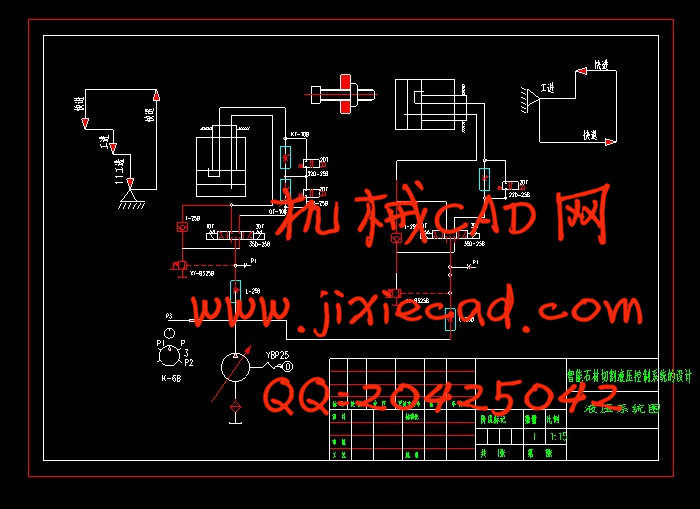
作为现代机械设备实现传动与控制的重要技术手段,液压技术在国民经济各领域得到了广泛的应用。与其他传动控制技术相比,液压技术具有能量密度高﹑配置灵活方便﹑调速范围大﹑工作平稳且快速性好﹑易于控制并过载保护﹑易于实现自动化和机电体化整合﹑系统设计制造和使用维护方便等多种显著的技术优势,因而使其成为现代机械工程的基本技术构成和现代控制工程的基本技术要素。智能石材切割机是加工各种石材的主要设备,适用于各类石材厂的石材的加工,如下料、开孔、开槽、拉伸等。本文根据智能石材切割机的用途﹑特点和要求,利用液压传动的基本原理,拟定出合理的液压系统图,再经过必要的计算来确定液压系统的参数,然后按照这些参数来选用液压元件的规格和进行系统的结构设计。智能石材切割机的液压系统呈长方形布置,外形新颖美观,动力系统采用液压系统,结构简单、紧凑、动作灵敏可靠。该机并设有脚踏开关,可实现半自动工艺动作的循环。液压传动和气压传动称为流体传动,是根据17世纪帕斯卡提出的液体静压力传动原理而发展起体传动技术水平的高低已成为一个国家工业发展水平的重要标志。
第一个使用液压原理的是1795年英国约瑟夫·布拉曼(Joseph Bram,以水压机的形式将其应用于工业上,诞生了世界上第一台水压机。1905年他又将工作介质水改为油,进一步得到改善。 我国的液压工业开始于20世纪50年代,液压元件最初应用于机床和锻压设备。60年代获得较大发展,已渗透到各个工业部门,在机床、工程机械、冶金、农业机械、汽车、船舶、航空、石油以及军工等工业中都得到了普遍的应用。当前液压技术正向高压、高速、大功率、高效率、低噪声、低能耗、长寿命、高度集成化等方向发展。同时,新元件的应用、系统计算助设计、计算机仿真和优化、微机控制等工作,也取得了显著成果。目前,我国的液压件已从低压到高压形成系列,并生产出许多新型元件,如插装 式锥阀、电液比例阀、电液伺服阀、电业数字控制阀等。我国机械工业在认真消化、推广国外引进的先进液压技术的同时,大力研制、开发国产液压件新产品,加强产品质量可靠性和新技术应用的研究,积极采用国际标准,合理调整产品结构,对一些性能差而且不符合国家标准的液压件产品,采用逐步淘汰的措施。由此可见,随着科学技术的迅速发展,液压技术将获得进一步发展,在各种机械设备上的应用将更加广泛。随着经济的发展和人们生活水平的提要求也进一步提高,因此作为高档次的居家装修材料——石材的需求量也逐年增加,由于天然石材的不规则性和石材资源的有限性使用使得石材的合理使用方法——石材切割技术得到迅速的发展。因此石材切割机的需求量也大量增加,国内外各种高性能的石材切割机种类很多,但是价格也极为昂贵,不适合我省大量中小型企业的需求,设计出在性能上满足中小企业要求的经济型石材切割机就显得尤为迫切.近年来我国引进了不少石材切割机,其机械性能和技术参数在不同程度上反映出石材切割技术的现代水平。目前在石材切割机国产化过程中,调查研究使用情况和存在问题,吸收其合理的先进的技术参数和机械结构,改进不足之处,对研制新颖,可靠,先进的设备,改变我国石材切割技术的落后状态,关键的一招,为了满足社会的需求,各国争先恐后的研制出不同得石材切割机来弥补现在石材切割机的不足,主要有:
1.单臂石材切割机单臂石材切割机凭借其结构紧凑,工作平稳,操纵轻便
灵活,安装维修方便的特点在石材加工中得到广泛地应用。该机主要用于小型石材加工厂,石材市场,板材经销商,现场加工及建筑单位现场施工。
2.移动式石材切割机
该机可直接在荒山矿料上直接切割加工生产各种规格板材,可彻底淘汰取代传统炸药与凿岩等开采方式。该机可直接安装在矿床上,自动切割加工各种石材,效果与传统锯石机完全一样。该机操作灵活,安装方便,加工效率快,板材成品率高。
3.DBS-1双向石材切割机
该机为单柱臂式,工作台液压推进,无级调速,结构先进合理,操作方便,维修容易,适于切割块度较小的荒料,是各类石材企业,特别是乡镇企业理想的石材加工设备。切割荒料的最大规格为长2.1米,宽1.1米,高1.3米,能切割在长度方向上拼接的荒料。该机主要切割大理石,也可切割花岗石等材料。
4.超薄型石材切割机
该机可锯10mm以下的石材,该机具有手动和自控两种功能,可任意选择锯片,工作台移动行程大,分片准确,板面误差小于0.5mm, 锯片最小厚度达6mm。
5.数控超薄型天然复合石材切割机
该机主要用来切割花岗岩,大理石,大面积超薄型石材,主要优点:
1.运动平稳,
2.金刚石工具刀口小,石材利用率高,能节省石材资源和能源。
3.石材表面切割质量好尺寸精度高,废品率低.。
4.综合生成成本低。
5能切割高档次的超薄型天然复合材。
6.电动石材切割机
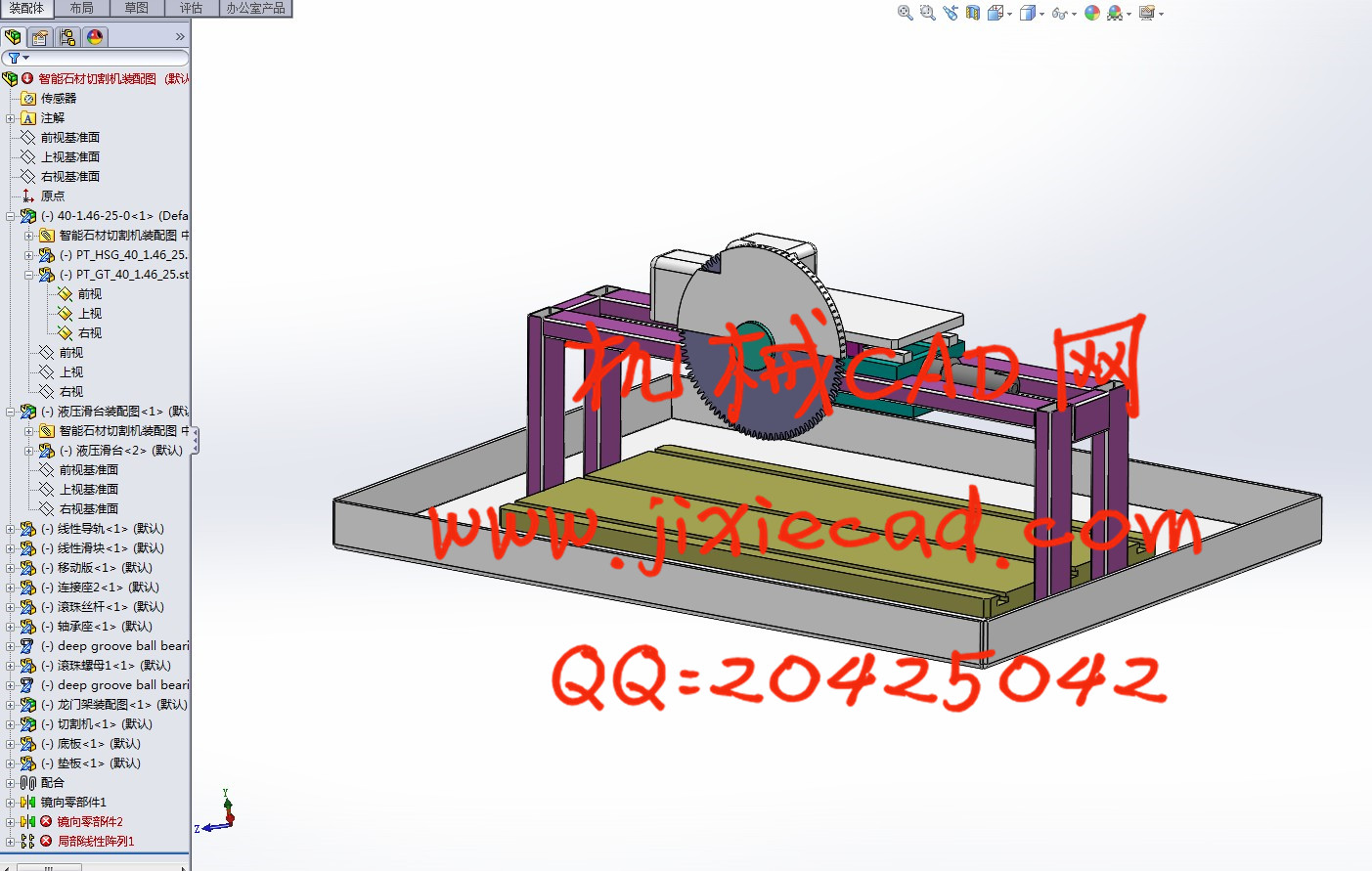
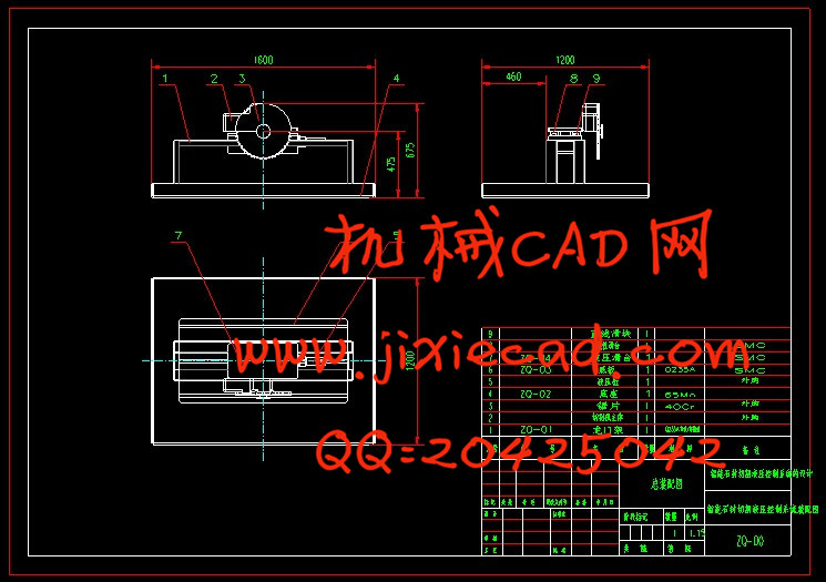
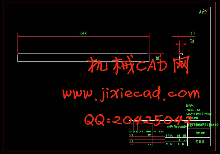
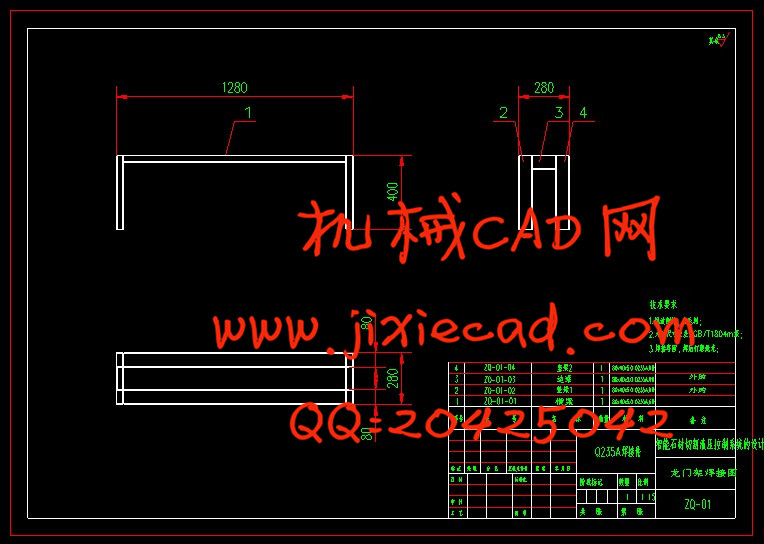
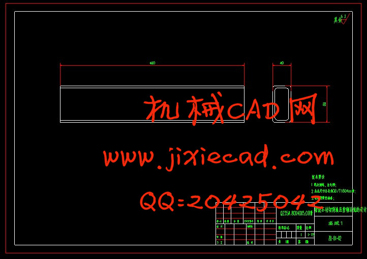
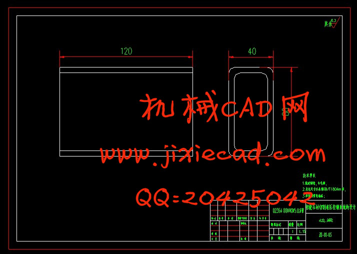
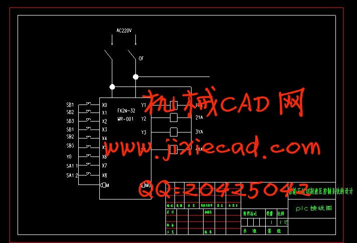
该机适用于建筑装潢,石材加工,对水磨石,大理石,花岗岩,玻璃,水泥制版等含硅酸盐的非金属脆性材料进行切割,开槽作业,它具有切削效率高,加工质量好,使用简便,劳动强度低的特点。综合各种石材切割机,我所设计的石材切割机采用全液压系统,设备由操作面板,电气控制装置,动力装置,机械装置和状态检测控制装置五大部分组成,机械装置包括翻转式回转工作台,床身平移装置,横梁,圆锯片拖板等构成,整套设备安装在钢筋混凝土造成的基础上,床身平移行走和切割,,行走通过电动机,减速器,齿轮,齿条啮合传动,圆锯片旋转采用带轮传动,圆锯片升降由滑板升降液压装置实现精准控制,横梁上装有可调位置的行程开关,床身横移切割的位移量由刻度尺示读床身平移导轨上安装有磁栅尺和读数头组成的位移检测装置,反馈床身的位移数据由PLC实现分片控制,以使整套设备在自动控制系统的作用下按程序完成加工工序。在操作过程中分为手动和自动,自动按钮按下后刀盘向下下降一个切削量,接着刀盘向左切削石材,刀盘到达左限位开关时,停止右移,又下降一个切削量,如此反复,直到刀盘在下降中碰到下限位开关时,停止下降并向相反方向切割最后一刀,以保证石材根部切割完整。
关键词: 智能石材切割 机械设备 切削 切割 PLC控制
absraote
作为现代机械设备实现传动与控制的重要技术手段,液压技术在国民经济各领域得到了广泛的应用。与其他传动控制技术相比,液压技术具有能量密度高﹑配置灵活方便﹑调速范围大﹑工作平稳且快速性好﹑易于控制并过载保护﹑易于实现自动化和机电体化整合﹑系统设计制造和使用维护方便等多种显著的技术优势,因而使其成为现代机械工程的基本技术构成和现代控制工程的基本技术要素。智能石材切割机是加工各种石材的主要设备,适用于各类石材厂的石材的加工,如下料、开孔、开槽、拉伸等。本文根据智能石材切割机的用途﹑特点和要求,利用液压传动的基本原理,拟定出合理的液压系统图,再经过必要的计算来确定液压系统的参数,然后按照这些参数来选用液压元件的规格和进行系统的结构设计。智能石材切割机的液压系统呈长方形布置,外形新颖美观,动力系统采用液压系统,结构简单、紧凑、动作灵敏可靠。该机并设有脚踏开关,可实现半自动工艺动作的循环。液压传动和气压传动称为流体传动,是根据17世纪帕斯卡提出的液体静压力传动原理而发展起体传动技术水平的高低已成为一个国家工业发展水平的重要标志。
第一个使用液压原理的是1795年英国约瑟夫·布拉曼(Joseph Bram,以水压机的形式将其应用于工业上,诞生了世界上第一台水压机。1905年他又将工作介质水改为油,进一步得到改善。 我国的液压工业开始于20世纪50年代,液压元件最初应用于机床和锻压设备。60年代获得较大发展,已渗透到各个工业部门,在机床、工程机械、冶金、农业机械、汽车、船舶、航空、石油以及军工等工业中都得到了普遍的应用。当前液压技术正向高压、高速、大功率、高效率、低噪声、低能耗、长寿命、高度集成化等方向发展。同时,新元件的应用、系统计算助设计、计算机仿真和优化、微机控制等工作,也取得了显著成果。目前,我国的液压件已从低压到高压形成系列,并生产出许多新型元件,如插装 式锥阀、电液比例阀、电液伺服阀、电业数字控制阀等。我国机械工业在认真消化、推广国外引进的先进液压技术的同时,大力研制、开发国产液压件新产品,加强产品质量可靠性和新技术应用的研究,积极采用国际标准,合理调整产品结构,对一些性能差而且不符合国家标准的液压件产品,采用逐步淘汰的措施。由此可见,随着科学技术的迅速发展,液压技术将获得进一步发展,在各种机械设备上的应用将更加广泛。随着经济的发展和人们生活水平的提要求也进一步提高,因此作为高档次的居家装修材料——石材的需求量也逐年增加,由于天然石材的不规则性和石材资源的有限性使用使得石材的合理使用方法——石材切割技术得到迅速的发展。因此石材切割机的需求量也大量增加,国内外各种高性能的石材切割机种类很多,但是价格也极为昂贵,不适合我省大量中小型企业的需求,设计出在性能上满足中小企业要求的经济型石材切割机就显得尤为迫切.近年来我国引进了不少石材切割机,其机械性能和技术参数在不同程度上反映出石材切割技术的现代水平。目前在石材切割机国产化过程中,调查研究使用情况和存在问题,吸收其合理的先进的技术参数和机械结构,改进不足之处,对研制新颖,可靠,先进的设备,改变我国石材切割技术的落后状态,关键的一招,为了满足社会的需求,各国争先恐后的研制出不同得石材切割机来弥补现在石材切割机的不足,主要有:
1.单臂石材切割机单臂石材切割机凭借其结构紧凑,工作平稳,操纵轻便
灵活,安装维修方便的特点在石材加工中得到广泛地应用。该机主要用于小型石材加工厂,石材市场,板材经销商,现场加工及建筑单位现场施工。
2.移动式石材切割机
该机可直接在荒山矿料上直接切割加工生产各种规格板材,可彻底淘汰取代传统炸药与凿岩等开采方式。该机可直接安装在矿床上,自动切割加工各种石材,效果与传统锯石机完全一样。该机操作灵活,安装方便,加工效率快,板材成品率高。
3.DBS-1双向石材切割机
该机为单柱臂式,工作台液压推进,无级调速,结构先进合理,操作方便,维修容易,适于切割块度较小的荒料,是各类石材企业,特别是乡镇企业理想的石材加工设备。切割荒料的最大规格为长2.1米,宽1.1米,高1.3米,能切割在长度方向上拼接的荒料。该机主要切割大理石,也可切割花岗石等材料。
4.超薄型石材切割机
该机可锯10mm以下的石材,该机具有手动和自控两种功能,可任意选择锯片,工作台移动行程大,分片准确,板面误差小于0.5mm, 锯片最小厚度达6mm。
5.数控超薄型天然复合石材切割机
该机主要用来切割花岗岩,大理石,大面积超薄型石材,主要优点:
1.运动平稳,
2.金刚石工具刀口小,石材利用率高,能节省石材资源和能源。
3.石材表面切割质量好尺寸精度高,废品率低.。
4.综合生成成本低。
5能切割高档次的超薄型天然复合材。
6.电动石材切割机
该机适用于建筑装潢,石材加工,对水磨石,大理石,花岗岩,玻璃,水泥制版等含硅酸盐的非金属脆性材料进行切割,开槽作业,它具有切削效率高,加工质量好,使用简便,劳动强度低的特点。综合各种石材切割机,我所设计的石材切割机采用全液压系统,设备由操作面板,电气控制装置,动力装置,机械装置和状态检测控制装置五大部分组成,机械装置包括翻转式回转工作台,床身平移装置,横梁,圆锯片拖板等构成,整套设备安装在钢筋混凝土造成的基础上,床身平移行走和切割,,行走通过电动机,减速器,齿轮,齿条啮合传动,圆锯片旋转采用带轮传动,圆锯片升降由滑板升降液压装置实现精准控制,横梁上装有可调位置的行程开关,床身横移切割的位移量由刻度尺示读床身平移导轨上安装有磁栅尺和读数头组成的位移检测装置,反馈床身的位移数据由PLC实现分片控制,以使整套设备在自动控制系统的作用下按程序完成加工工序。在操作过程中分为手动和自动,自动按钮按下后刀盘向下下降一个切削量,接着刀盘向左切削石材,刀盘到达左限位开关时,停止右移,又下降一个切削量,如此反复,直到刀盘在下降中碰到下限位开关时,停止下降并向相反方向切割最后一刀,以保证石材根部切割完整。
关键词: 智能石材切割 机械设备 切削 切割 PLC控制
absraote
Pneumatic manipulator is a automated devices that can mimic the human hand and arm movements to do something,aslo can according to a fixed procedure to moving objects or control tools. It can replace the heavy labor in order to achieve the production mechanization and automation, and can work in dangerous working environments to protect the personal safety, Therefore widely used in machine building, metallurgy, electronics, light industry and atomic energy sectors.
This article is mainly of the pneumatic manipulator the overall design, and pneumatic design. This mechanism of manipulator includes cylinders and claws and connectors parts, it can move according to the due track on the movement of grabbing, carrying and unloading. The pneumatic part of the design is primarily to choose the right valves and design a reasonable pneumatic control loop, by controlling and regulating pressure, flow and direction of the compressed air to make it get the necessary strength, speed and changed the direction of movement in the prescribed procedure work.It can replace the heavy labor in order to achieve the production mechanization and automation, and can work in dangerous working environments to protect the personal safety, Therefore widely used in machine building, metallurgy, electronics, light industry and atomic .The principle, technical pare-maters, transmiting system and main parts structure of mincing ma-chine were introduced.The productingcapacity was analysed.Keywords Mincing machine Holds plate Cutting blade Transfer augerFixture design process of drilling pump cover and reaming holes is designed with 18H7 include part machining process design, process design and fixture three. In process design should first of all parts for analysis, to understand part of the process to design blank structure, and choose the good parts machining datum, design the process routes of the parts; then the parts of each step in the process to the size calculation, the key is to determine the craft equipment and the cutting dosage of each working procedure design; then the special fixture, the fixture for the various components of the design, such as the connecting part positioning devices, clamping element, a guide element, fixture and machine tools and other components; positioning error calculated by the analysis of fixture, jig structure the rationality and the deficiency, pay attention to improving and will design in.
Concurrent Engineering is the first to shorten product development cycles as a means to develop. Products will be characterized by the development, production engineering involved in the acts broken down into a series of tasks, such as market analysis, design, process design, production plans and equipment purchases, processing, quality assurance, testing and after sales service. These sub-tasks as far as possible and consider synchronous parallel to achieve improved design to shorten the cycle and improve quality, reduce costs, optimize the design purpose. It stressed that integrated, coordinated and parallel, namely: (1) management, design, production, and service of all project-related personnel and product information integration as a whole, and stressed that all relevant departments and the interests of the overall goal line (2) to the establishment of a competent and reasonable charge of the project personnel structure of the working group coordinated management model, by the Working Group in the ministries responsible for project elements, and the promotion of the coordination of tasks, (3) parallel processing stages of the work. According to the project in the different tasks of the linkages between the different ministries mandate of the elements of the work process can be completely overlap or duplication. In accordance with these principles, formulate a reasonable, and optimize the work plan, and the location in which the necessary settings assessment, the Working Group by the project implementation so that all sub-tasks in parallel, to move forward in an orderly manner, so as to ensure the smooth implementation of the whole project .
According to the traditional methods of work, the work of the various stages in a row serial. In such a product development approach, divorced from each other at various stages, are not related, resulting in increased design error, and difficult to discover such a design rework, to lengthen the development cycle, adding to the costs.
This paper discusses the meat processing machinery - crusher working principle, main technical parameters, transmission system, the typical parts of the structure design and production capacity analysis.
Small twisted paper broken machine for ordinary home, not only can be used for minced meat, can also be used with crushed peanuts, crushed ice, spices and other food, small power requirements, powered by the motor drive, reasonable structure design, can meet the family kitchen generally meat food consisting mainly of minced required.
Key word: pneumatic manipulator cylinder pneumatic loop Four degrees of freedom
目 录
1绪论 9
1.1课题的来源与研究的目的与意义.............................................................................10
1.2液压传动在机械行业中的应用......................................................................11
1.3液压系统的基本组成............................................................................................12
1.4 液压传动的优缺点...............................................................................................13
1.5液压传动技术的发展及应用...........................................................................14
2液压缸的负载以及工况分析......................................................................................15
2.1 液压缸的工作负载 16
2.2 液压缸的摩擦阻力 17
2.3 液压缸的惯性负荷 18
3负载图和速度图............................................................................................................18
4液压缸的设计及计算...................................................................................................19
4.1液压缸的类型及结构形式.....................................................................................19
4.2 液压缸的工作压力...............................................................................................20
4.3 液压缸尺寸计算...................................................................................................21
4.4液压缸各工作阶段的压力、流量和功率计算....................................................21
4.5 绘制液压缸的工况图............................................................................................21
5拟定液压系统图..............................................................................................................22
5.1选择液压基本回路.................................................................................................22
5.2 组成系统图............................................................................................................22
6选择液压元件..................................................................................................................23
6.1确定液压泵的容量及电机功率.............................................................................24
6.2控制阀的选择.........................................................................................................25
6.3确定油管直径..........................................................................................................26
6.4确定油箱容积..........................................................................................................27
7液压系统的性能验算.......................................................................................................27
7.1液压系统的压力损失计算....................................................................................28
7.2液压系统的热量温升计算.....................................................................................29
结论 30
参考文献 31
致谢....................................................................................................................................32