设计简介
摘 要
连杆机构广泛运用于选多级其中,在我们的生活中起着重要的作用;如平衡吊的工作原理、刨床的直线插补作原理等等。连杆的杆机构又称低副机构,是机械的组成部分中的一类,指由若干(两个以上)有确定相对运动的构件用低副(转动副或移动副)联接组成的机构。平面连杆机构中最基本也是应用最广泛的一种型式是由四个构件组成的平面四杆机构。由于机构中的多数构件呈杆状,所以常称杆状构件为杆。低副是面接触,耐磨损;加上转动副和移动副的接触表面是圆柱面和平面,制造简便,易于获得较高的制造精度。连杆机构广泛应用于各种机械和仪表中。因此,平面连杆机构在各种机械和仪器中获得广泛应用。连杆机构的缺点是:低副中存在间隙,数目较多的低副会引起运动累积误差;而且它的设计比较复杂,不易精确地实现复杂地运动规律。
连杆机构构件运动形式多样,如可实现转动、摆动、移动和平面或空间复杂运动,从而可用于实现已知运动规律和已知轨迹。此外,低副面接触的结构使连杆机构具有以下一些优点:运动副单位面积所受压力较小,且面接触便于润滑,故磨损减小;制造方便,易获得较高的精度;两构件之间的接触是靠本身的几何封闭来维系的,它不象凸轮机构有时需利用弹簧等力封闭来保持接触。因此,平面连杆机构广泛应用于各种机械、仪表和机电产品中。平面连杆机构的缺点是:一般情况下,只能近似实现给定的运动规律或运动轨迹,且设计较为复杂;当给定的运动要求较多或较复杂时,需要的构件数和运动副数往往较多,这样就使机构结构复杂,工作效率降低,不仅发生自锁的可能性增加,而且机构运动规律对制造、安装误差的敏感性增加;机构中作复杂运动和作往复运动的构件所产生的惯性力难以平衡,在高速时将引起较大的振动和动载荷,故连杆机构常用于速度较低的场合。
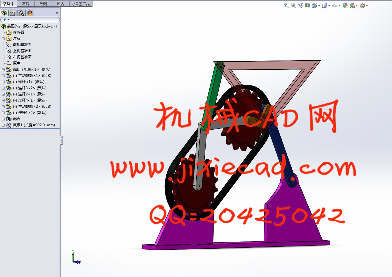
计算机与网络技术的飞速发展, 已经逐步改变了传统面对面的教学方式。基于Internet的网络教学模式,具有交互性好、教学过程不受时空限制的特点,可以实现教学资源的共享,满足人 们随时随地学习的需求。平面连杆机构是一种应用十分广泛的机构,对其进行仿真与分析是《机械原理》教学中的重点和难点。传统教学模式下线条状的机构简图虽 然可以进行机构仿真,但所实现的机构仿真不但缺乏三维真实感,而且分析结果的精度也不高。SW是一款CAD/CAM/CAE高度集成化的三维软件, 它具有强大的三维建模和分析仿真功能。因此,开发基于SW系统的平面连杆机构网络教学系统具有很强的应用价值和现实意义 。 本文以平面连杆机构为研究对象,分析目前国内外相关研究现状,在其他研究人员的研究基础之上,研究并开发了基于SW的平面连杆机构网络教学系统。该 系统主要实现了在网络环境下利用SW进行平面连杆机构的三维参数化建模、干涉检查、自动装配和运动仿真等功能,具有方便、交互、形象的特点,最大程 度上实现了资源的共享。 本文以SW软件为平台,借助SW工具箱和网络技术,围绕SW的远程操作、数据库系统的建立、图形文件的交互以及服务器对机 构模型文件的管理等技术进行研究,主要研究内容如下: 1、对网络教学系统各功能模块进行需求分析,建立基于B/S模式的三层网络结构体系; 2、研究Web数据库系统的建立和维护,利用Access创建Web数据库,实现机构设计参数和用户信息的有效管理。 3、对COM组件和ActiveX组件技术进行研究和分析,解决网络服务器与SW系统之间的数据通讯,实现对SW系统的远程操作; 4、对SW二次开发技术进行深入研究,利用SW/TOOLKIT工具箱开发网络教学系统的各个功能模块,实现自动装配。本设计采用连杆机构做的直线引导机构设计与分析。
二、Pick to
Consisting of the rod of the linkage mechanism is widely used to multistage which, in our lives plays an important role, such as balance crane work principle, planer linear interpolation principle and so on. The connecting rod mechanism and low pair mechanism, mechanical part of a class, defined by a number of (two or more) to determine the relative motion of the component with low side (rotating or moving pair coupling mechanism. Planar linkage mechanism in the basic and applied the most extensive a type is composed of four components of plane four bar mechanism. Because most of members is in the shape of a rod, so often called rod member bar. Low side is the surface contact, wear resistance, and the rotating pair and shift Dynamic contact surface is a cylindrical surface and a plane surface, easy manufacture, easy to obtain high manufacturing accuracy. Linkage mechanism widely used in all kinds of machinery and instrument. Therefore, planar linkage in various kinds of machines and instruments obtained widely application. The shortcomings of connecting rod mechanism is: low side of gap, a large number of low side will cause cumulative motion error; and its design is more complex, not easy to accurately realize complex motions.
Even in closed geometry contact between linkage movement of components in various forms, such as the rotation, swing, mobile and plane or space complex motion, which can be used to achieve the known movement and the known trajectory. In addition, low side surface contact structure of the connecting rod mechanism has the following advantages: kinematic pairs per unit area pressure is smaller, and the surface contact for lubrication, so wear decreases, making convenient, easy to obtain high accuracy; two components is to rely on itself to sustain, it does not look like the cam mechanism may be required by the spring force closed to keep in touch. Because of this, the planar linkage mechanism is widely used in all kinds of machinery, instrument and mechanical and electrical products. The plane The shortcomings of the rod mechanism is: in general, can only approximate the given movement or the trajectory, and the design is more complex. When a given movement to demand more and more complex, need the number of components and the motion pair number more often, such mechanism makes the structure complex, work efficiency is reduced, not only increase the possibility of self-locking and the motion law of manufacturing, installation error sensitivity increased; mechanism for complex motion and the inertia force generated by the reciprocating motion of the components are difficult to be balanced, at high speed will cause large vibration and dynamic load, so the connecting rod mechanism is used in low speed occasion.
The rapid development of computer and network technology, has gradually changed the traditional face-to-face teaching method. Based on the teaching mode of the Internet network, with a good interactive, teaching process is not limited by time and space can realize the sharing of teaching resources, meet the needs of people at any time with learning. Planar linkage mechanism is a widely used mechanism, the for simulation and analysis of mechanical principle of < > teaching is the key point and the difficulty. The traditional teaching mode line strip mechanism diagrams although may mechanism simulation, but the mechanism simulation not only a lack of true three-dimensional sense, and analysis the results of precision Is not high.SW is a CAD / CAM / CAE highly integrated 3D software. It has powerful function in three-dimensional modeling, analysis and simulation. Therefore, the development of Planar Linkage Network Teaching System Based on the SW system has very strong application value and practical significance. The planar linkage mechanism as the research object, analysis of the present research situation at home and abroad, based on the research foundation of other researchers. Research and development of the planar linkage network teaching system based on the SW. The system mainly realizes under the network environment by SW three-dimensional parametric modeling of planar linkage, interference check, automatic Assembly and motion simulation function, and has the advantages of convenient, interaction, image features, full of realized resources sharing. This paper to SW platform, with the aid of SW toolbox and network technology, remote operation around the SW, the establishment of the database system, graphics file interaction and server on the machine frame model file management technology research, the main research contents are as follows: 1, the function modules of the network teaching system needs analysis, establish the three layer network system which is based on B / S mode; 2, research of Web database system establishment and maintenance, access to create web data Library, realize the effective management of the design parameters and the user information. 3, to com and ActiveX component technology were research and analysis, solves the data communication between a web server and a sw system, to realize the remote operation of the SW system; 4, the secondary development technology of SW were in-depth study, using SW/TOOLKIT toolbox to develop network teaching system each function module, realization of automatic assembly. The design uses linkage mechanism as the linear guide mechanism design and analysis.
目 录
一 摘 要...................................................................................................2
二 连杆机构概述...........................................................................................9
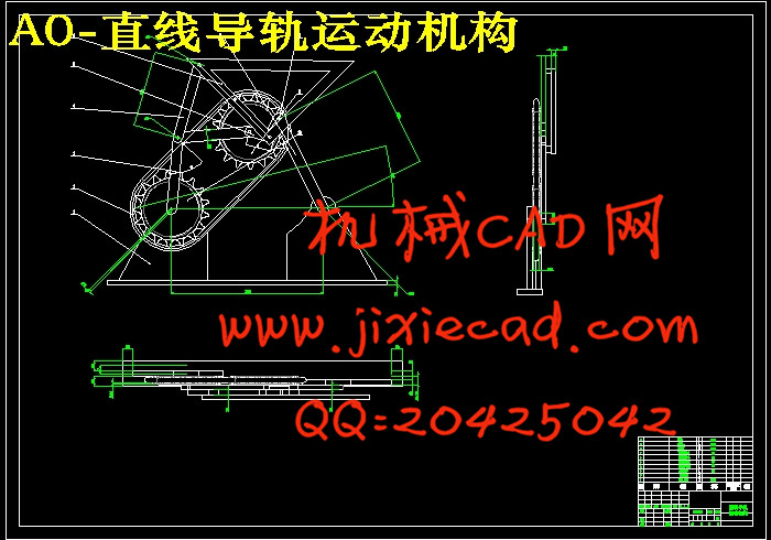
三 直线引导机构的原理与结构分析.........................................................11
四 直线引导机构的运动分析.....................................................................12
4.1 直线引导机构自由度的计算..........................................................12
五 直线引导机构的结构设计.....................................................................14
5.1 工作条件的确定................................................................................14
5.2 总体设计分析....................................................................................
5.3 链传动的设计...................................................................................
5.4 电机的选择.......................................................................................
5.5 减速器的选择..................................................................................
5.6 连传动的设计的选择.......................................................................
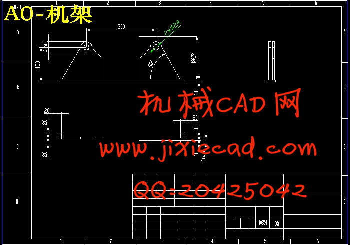
5.7 底座的设计..........................................................................................
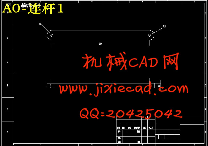
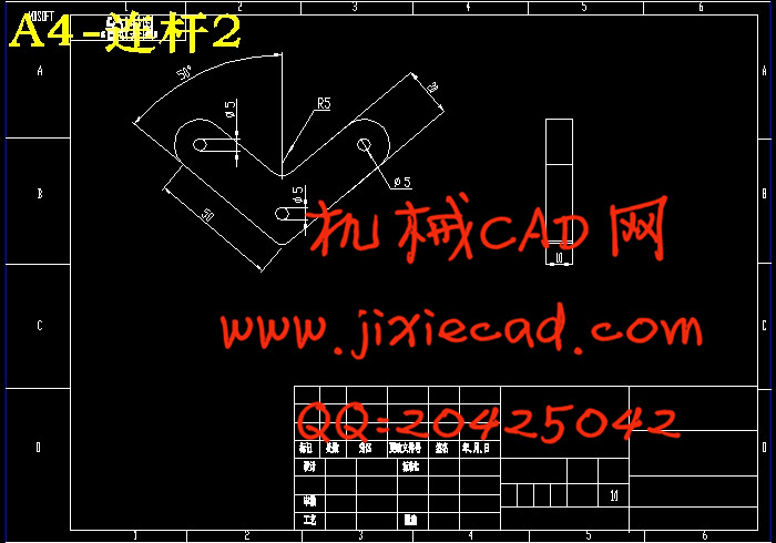
5.8 各杆长度设计 ....................................................................................
六 直线引导机构的有限元分析...................................................................
七 结 论......................................................................................................
八 参考文献..................................................................................................
九 谢 辞......................................................................................................
连杆机构广泛运用于选多级其中,在我们的生活中起着重要的作用;如平衡吊的工作原理、刨床的直线插补作原理等等。连杆的杆机构又称低副机构,是机械的组成部分中的一类,指由若干(两个以上)有确定相对运动的构件用低副(转动副或移动副)联接组成的机构。平面连杆机构中最基本也是应用最广泛的一种型式是由四个构件组成的平面四杆机构。由于机构中的多数构件呈杆状,所以常称杆状构件为杆。低副是面接触,耐磨损;加上转动副和移动副的接触表面是圆柱面和平面,制造简便,易于获得较高的制造精度。连杆机构广泛应用于各种机械和仪表中。因此,平面连杆机构在各种机械和仪器中获得广泛应用。连杆机构的缺点是:低副中存在间隙,数目较多的低副会引起运动累积误差;而且它的设计比较复杂,不易精确地实现复杂地运动规律。
连杆机构构件运动形式多样,如可实现转动、摆动、移动和平面或空间复杂运动,从而可用于实现已知运动规律和已知轨迹。此外,低副面接触的结构使连杆机构具有以下一些优点:运动副单位面积所受压力较小,且面接触便于润滑,故磨损减小;制造方便,易获得较高的精度;两构件之间的接触是靠本身的几何封闭来维系的,它不象凸轮机构有时需利用弹簧等力封闭来保持接触。因此,平面连杆机构广泛应用于各种机械、仪表和机电产品中。平面连杆机构的缺点是:一般情况下,只能近似实现给定的运动规律或运动轨迹,且设计较为复杂;当给定的运动要求较多或较复杂时,需要的构件数和运动副数往往较多,这样就使机构结构复杂,工作效率降低,不仅发生自锁的可能性增加,而且机构运动规律对制造、安装误差的敏感性增加;机构中作复杂运动和作往复运动的构件所产生的惯性力难以平衡,在高速时将引起较大的振动和动载荷,故连杆机构常用于速度较低的场合。
计算机与网络技术的飞速发展, 已经逐步改变了传统面对面的教学方式。基于Internet的网络教学模式,具有交互性好、教学过程不受时空限制的特点,可以实现教学资源的共享,满足人 们随时随地学习的需求。平面连杆机构是一种应用十分广泛的机构,对其进行仿真与分析是《机械原理》教学中的重点和难点。传统教学模式下线条状的机构简图虽 然可以进行机构仿真,但所实现的机构仿真不但缺乏三维真实感,而且分析结果的精度也不高。SW是一款CAD/CAM/CAE高度集成化的三维软件, 它具有强大的三维建模和分析仿真功能。因此,开发基于SW系统的平面连杆机构网络教学系统具有很强的应用价值和现实意义
二、Pick to
Consisting of the rod of the linkage mechanism is widely used to multistage which, in our lives plays an important role, such as balance crane work principle, planer linear interpolation principle and so on. The connecting rod mechanism and low pair mechanism, mechanical part of a class, defined by a number of (two or more) to determine the relative motion of the component with low side (rotating or moving pair coupling mechanism. Planar linkage mechanism in the basic and applied the most extensive a type is composed of four components of plane four bar mechanism. Because most of members is in the shape of a rod, so often called rod member bar. Low side is the surface contact, wear resistance, and the rotating pair and shift Dynamic contact surface is a cylindrical surface and a plane surface, easy manufacture, easy to obtain high manufacturing accuracy. Linkage mechanism widely used in all kinds of machinery and instrument. Therefore, planar linkage in various kinds of machines and instruments obtained widely application. The shortcomings of connecting rod mechanism is: low side of gap, a large number of low side will cause cumulative motion error; and its design is more complex, not easy to accurately realize complex motions.
Even in closed geometry contact between linkage movement of components in various forms, such as the rotation, swing, mobile and plane or space complex motion, which can be used to achieve the known movement and the known trajectory. In addition, low side surface contact structure of the connecting rod mechanism has the following advantages: kinematic pairs per unit area pressure is smaller, and the surface contact for lubrication, so wear decreases, making convenient, easy to obtain high accuracy; two components is to rely on itself to sustain, it does not look like the cam mechanism may be required by the spring force closed to keep in touch. Because of this, the planar linkage mechanism is widely used in all kinds of machinery, instrument and mechanical and electrical products. The plane The shortcomings of the rod mechanism is: in general, can only approximate the given movement or the trajectory, and the design is more complex. When a given movement to demand more and more complex, need the number of components and the motion pair number more often, such mechanism makes the structure complex, work efficiency is reduced, not only increase the possibility of self-locking and the motion law of manufacturing, installation error sensitivity increased; mechanism for complex motion and the inertia force generated by the reciprocating motion of the components are difficult to be balanced, at high speed will cause large vibration and dynamic load, so the connecting rod mechanism is used in low speed occasion.
The rapid development of computer and network technology, has gradually changed the traditional face-to-face teaching method. Based on the teaching mode of the Internet network, with a good interactive, teaching process is not limited by time and space can realize the sharing of teaching resources, meet the needs of people at any time with learning. Planar linkage mechanism is a widely used mechanism, the for simulation and analysis of mechanical principle of < > teaching is the key point and the difficulty. The traditional teaching mode line strip mechanism diagrams although may mechanism simulation, but the mechanism simulation not only a lack of true three-dimensional sense, and analysis the results of precision Is not high.SW is a CAD / CAM / CAE highly integrated 3D software. It has powerful function in three-dimensional modeling, analysis and simulation. Therefore, the development of Planar Linkage Network Teaching System Based on the SW system has very strong application value and practical significance. The planar linkage mechanism as the research object, analysis of the present research situation at home and abroad, based on the research foundation of other researchers. Research and development of the planar linkage network teaching system based on the SW. The system mainly realizes under the network environment by SW three-dimensional parametric modeling of planar linkage, interference check, automatic Assembly and motion simulation function, and has the advantages of convenient, interaction, image features, full of realized resources sharing. This paper to SW platform, with the aid of SW toolbox and network technology, remote operation around the SW, the establishment of the database system, graphics file interaction and server on the machine frame model file management technology research, the main research contents are as follows: 1, the function modules of the network teaching system needs analysis, establish the three layer network system which is based on B / S mode; 2, research of Web database system establishment and maintenance, access to create web data Library, realize the effective management of the design parameters and the user information. 3, to com and ActiveX component technology were research and analysis, solves the data communication between a web server and a sw system, to realize the remote operation of the SW system; 4, the secondary development technology of SW were in-depth study, using SW/TOOLKIT toolbox to develop network teaching system each function module, realization of automatic assembly. The design uses linkage mechanism as the linear guide mechanism design and analysis.
目 录
一 摘 要...................................................................................................2
二 连杆机构概述...........................................................................................9
三 直线引导机构的原理与结构分析.........................................................11
四 直线引导机构的运动分析.....................................................................12
4.1 直线引导机构自由度的计算..........................................................12
五 直线引导机构的结构设计.....................................................................14
5.1 工作条件的确定................................................................................14
5.2 总体设计分析....................................................................................
5.3 链传动的设计...................................................................................
5.4 电机的选择.......................................................................................
5.5 减速器的选择..................................................................................
5.6 连传动的设计的选择.......................................................................
5.7 底座的设计..........................................................................................
5.8 各杆长度设计 ....................................................................................
六 直线引导机构的有限元分析...................................................................
七 结 论......................................................................................................
八 参考文献..................................................................................................
九 谢 辞......................................................................................................