设计简介
摘 要
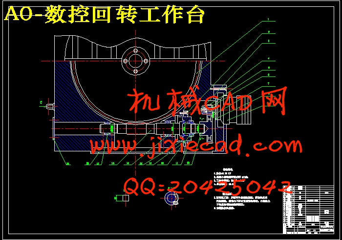
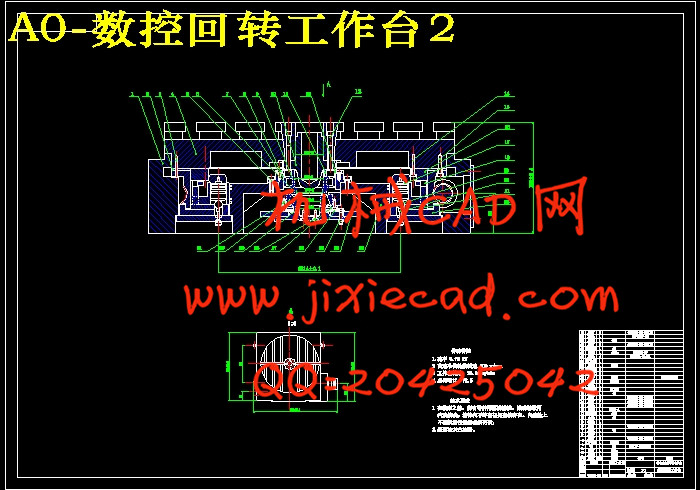
随着生产力水平的发展,数控技术越来越广泛的应用于各个领域。数控机车是数控技术最普遍的应用。数控车床今后将向中高挡发展,中档采用普及型数控刀架配套,高档采用动力型刀架,兼有液压刀架、伺服刀架、立式刀架等品种,预计近年来对数控刀架需求量将大大增加。但是数控回转工作台更有发展前途,它是一种可以实现圆周进给和分度运动的工作台,它常被使用于卧式的镗床和加工中心上,可提高加工效率,完成更多的工艺,它主要由原动力、齿轮传动、蜗杆传动、工作台等部分组成,并可进行间隙消除和蜗轮加紧,是一种很实用的加工工具。本课题主要介绍了它的原理和机械结构的设计,并对以上部分运用AUTOCAD做图,最后是对数控回转工作台提出的一点建议。
关键词:数控回转工作台;齿轮传动;蜗杆传动;间隙消除;蜗轮加紧
Abstract
With the level of development of productive forces, NC technology is more and more widely used in various fields. NC locomotive technology is the most widespread application. Numerical control there is in the future lathe to in will develop, the middle-grade to adopt popular numerical control knife rest form a complete set, adopt the motive force type knife rest top-grandly, have such varieties as knife rest of hydraulic pressure, servo knife rest, vertical knife rest, etc. concurrently, it is estimated that will increase to numerical control knife rest demand greatly in recent years. The development trend of the Numerical control rotary table is: With the development of numerical control lathe, numerical control knife rest begin to change one hundred sheets , electric liquid is it urge and urge direction develop while being servo to make up fast. Some originally design and is it continue electricity to use to four worker location vertical electronic machinery of knife rest mainly- exposed to control system control some designs. And use AUTOCAD to pursue to the above part, have a more ocular knowledge of electronic knife rest. The last proposition has put forward the suggestion and measure to Numerical control rotary table.
Key words:Numerical control rotary table; Gear drive;Worm drive;Gap elimination; The worm gear steps up.
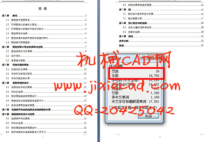
目 录
第1章 绪论 1随着生产力水平的发展,数控技术越来越广泛的应用于各个领域。数控机车是数控技术最普遍的应用。数控车床今后将向中高挡发展,中档采用普及型数控刀架配套,高档采用动力型刀架,兼有液压刀架、伺服刀架、立式刀架等品种,预计近年来对数控刀架需求量将大大增加。但是数控回转工作台更有发展前途,它是一种可以实现圆周进给和分度运动的工作台,它常被使用于卧式的镗床和加工中心上,可提高加工效率,完成更多的工艺,它主要由原动力、齿轮传动、蜗杆传动、工作台等部分组成,并可进行间隙消除和蜗轮加紧,是一种很实用的加工工具。本课题主要介绍了它的原理和机械结构的设计,并对以上部分运用AUTOCAD做图,最后是对数控回转工作台提出的一点建议。
关键词:数控回转工作台;齿轮传动;蜗杆传动;间隙消除;蜗轮加紧
Abstract
With the level of development of productive forces, NC technology is more and more widely used in various fields. NC locomotive technology is the most widespread application. Numerical control there is in the future lathe to in will develop, the middle-grade to adopt popular numerical control knife rest form a complete set, adopt the motive force type knife rest top-grandly, have such varieties as knife rest of hydraulic pressure, servo knife rest, vertical knife rest, etc. concurrently, it is estimated that will increase to numerical control knife rest demand greatly in recent years. The development trend of the Numerical control rotary table is: With the development of numerical control lathe, numerical control knife rest begin to change one hundred sheets , electric liquid is it urge and urge direction develop while being servo to make up fast. Some originally design and is it continue electricity to use to four worker location vertical electronic machinery of knife rest mainly- exposed to control system control some designs. And use AUTOCAD to pursue to the above part, have a more ocular knowledge of electronic knife rest. The last proposition has put forward the suggestion and measure to Numerical control rotary table.
Key words:Numerical control rotary table; Gear drive;Worm drive;Gap elimination; The worm gear steps up.
目 录
1.1 数控技术发展简史 2
1.2 机床数控化改造的必要性 2
1.3 机床数控化改造的内容及优缺点 4
1.4 数控系统的选择 4
1.5 数控改造中主要机械部件改装的探讨 5
1.6 数控技术发展趋势 6
第2章 数控回转工作台的原理与应用 7
2.1 数控回转工作的原理 9
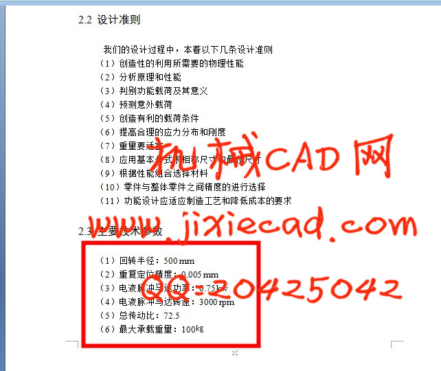
2.2 设计准则 10
2.3 主要技术参数 10
第3章 传动方案的确定 11
3.1 步进电机的原理 11
3.2 传动时应满足的要求 11
3.3 传动方案及其分系 12
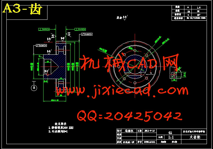
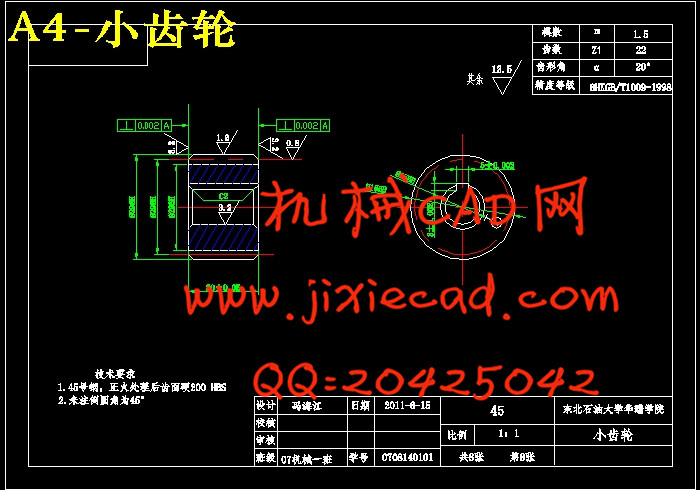
第4章 齿轮传动的设计 13
4.1 选择齿轮传动的类型 13
4.2 材料的选择 13
4.3 按齿面接触疲劳强度设计 15
4.4 确定齿轮的主要参数与主要尺寸 17
4.5 校核齿根弯曲疲劳强度 17
第5章 电液脉冲马达的选择及运动参数的计算 19
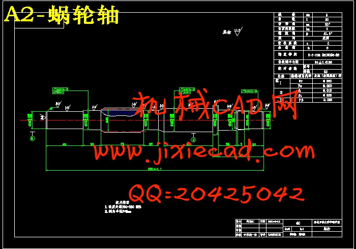
第6章 蜗轮蜗杆的设计与校核 21
6.1 选择蜗杆传动类型 21
6.2 材料的选择 21
6.3 按齿面接触疲劳强度设计 22
6.4 蜗杆与蜗轮的主要参数与几何尺寸 24
6.5 校核齿根弯曲疲劳强度 24
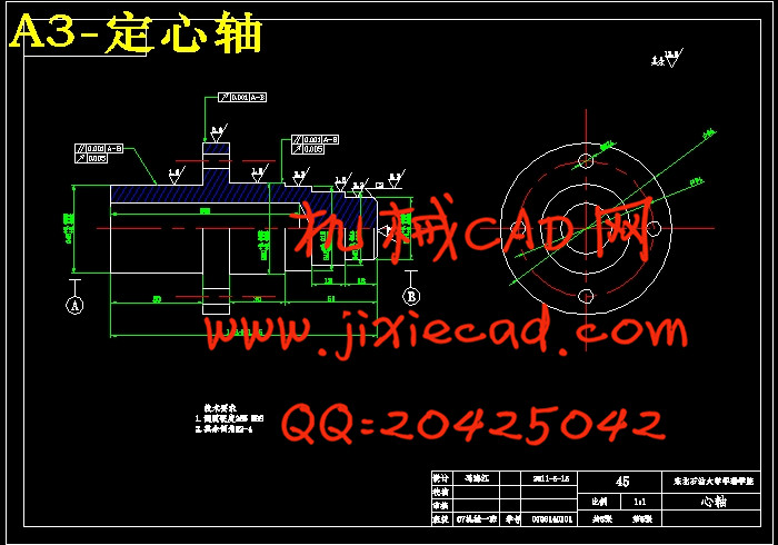
第7章 轴 26
7.1 轴的设计要求和设计步骤 26
7.2 轴的强度计算 27
第8章 轴上配合件的选用 29
8.1 齿轮上键的选取与校核 29
8.2 轴承的选用 29
第9章 结论 31
参考文献 32
致谢 33