设计简介
4L22柴油机机体顶面精铣床设计
摘要
本文主要介绍了4L22柴油机机体顶面精铣床的设计。研究的主要问题是4L22柴油机机体顶面精铣床外观图设计和夹具设计。根据4L22柴油机机体的结构、形状和尺寸特点,4L22柴油机机体顶面精铣床外观图设计选用了通用部件:铣削头、机械滑台等,配以专用的夹具和立柱、侧底座等基础部件,采用立式布局形式组成一组合铣床;夹具的设计,采用三基面组合定位,采用机动夹紧方式,使用液压斜楔夹紧装置完成工件夹紧。该设计方案具有设计制造周期短,生产率高,加工质量稳定,工人劳动强度低,产品更新时,组合铣床上的通用部件仍可重新利用组成新的组合机床等优点。经过分析和精度验算表明该设计方案能够满足4L22柴油机机体生产纲领要求,能够保证4L22柴油机机体顶面的加工精度和表面质量要求。关键词:铣削头;机械滑台;组合铣床;夹具
Design Fine Milling Machine Tool to Mill the 4L22 Diesel Engine Fuselage
Abstract
This article mainly introduced the design about the fine milling machine tool ,which was used to mill the top of the 4L22 diesel engine fuselage.It mainly focused on the design is the outward appearance chart and the jig.According to the diesel engine of the fuselage’s structure,shape, size, the design of the outward appearance chart, selected the interchangeable components,which includes the mechanical slip lable and the milling cutter unit, design the special-purpose jig and the basic parts of colum, side foundation to form a vertical complete milling machine tool. In the design of the jig, it used three basic plane combinations localization.Simultaneously,in order to reduces worker’s labor intensity and non-cutting time, using hydraulic pressure to clamp. With hydraulic pressure wedge clamp installment to complete the work piece clamping. This design proposal has many advantages,such as, the cycle of the design and manufacture is short, the cost of the manufacture is low,high productivity, stable processing accuracy, and the interchangeable components still can reuse to form a new complete milling machine tool ,when the product is renewal. Being analysed and precison computed, this milling machine tool can meet the product efficiency , processing accuracy and superficial demand.Key words:Milling cutter unit ; Mechanical slip lable ; Block milling machine tool ; Jig
目录
摘要…………………………………………………………………………………………Ⅰ
Abstract……………………………………………………………………………………...Ⅱ
第一章 绪论…………………………………………………………………………………1
1.1选题的背景、目的和意义 ……………………………………………………………………… 1
1.2 国内外研究现状分析 …………………………………………………………………………… 1
第二章 方案选择与论证……………………………………………………………………3
2.1确定方案……………………………………………………………………………………………3
2.2方案分析和选择……………………………………………………………………………………3
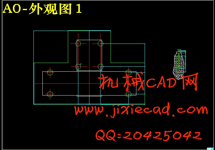
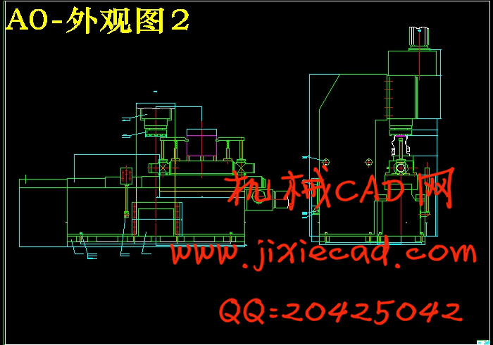
第三章 4L22柴油机机体顶面精铣床外观图设计…………………………………………4
3.1选取铣刀……………………………………………………………………………………………4
3.2选取动力部件………………………………………………………………………………………4
3.2.1计算铣削力……………………………………………………………………………………4
3.2.2选取主运动部件—铣削头……………………………………………………………………5
3.2.3选取进给运动部件—机械滑台………………………………………………………………6
3.2.4立柱尺寸确定…………………………………………………………………………………6
3.2.5中间底座尺寸确定……………………………………………………………………………7
3.2.6机床的工作循环………………………………………………………………………………7
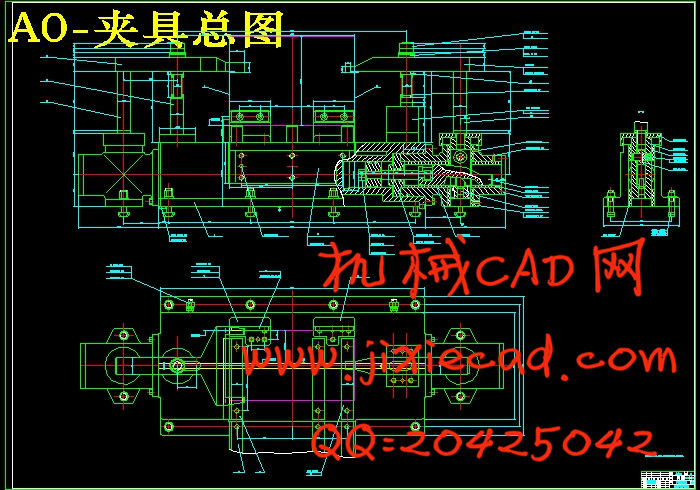
第四章 夹具设计…………………………………………………………………………….8
4.1确定夹具定位方案,设计定位元件 ………………………………………………………………8
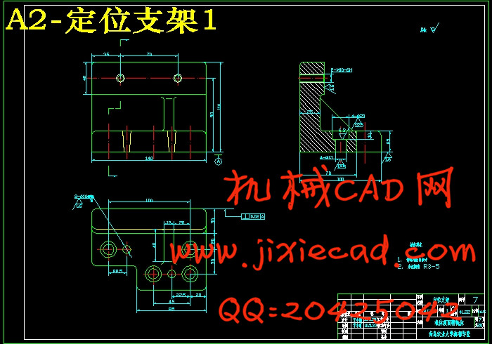
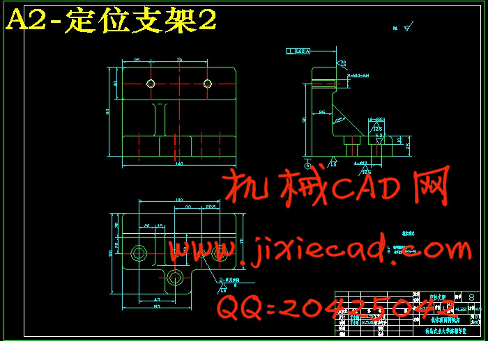
4.1.1定位方案的确定 ………………………………………………………………………………8
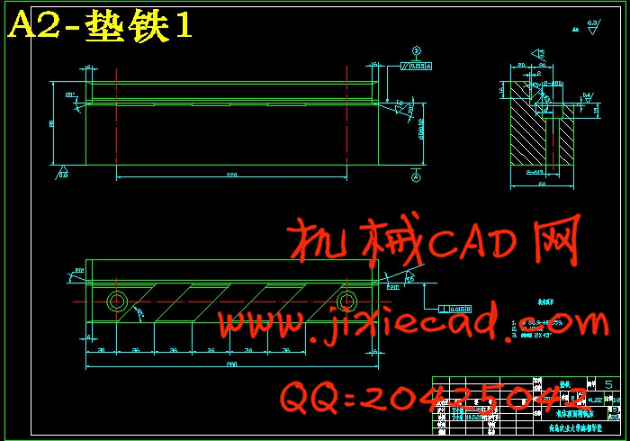
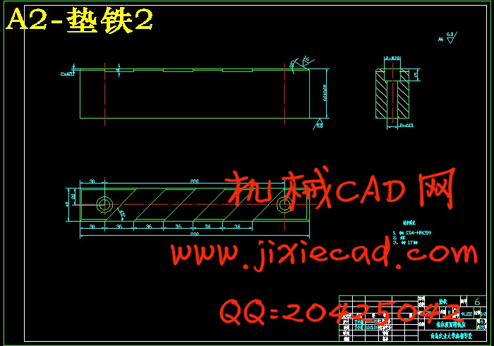
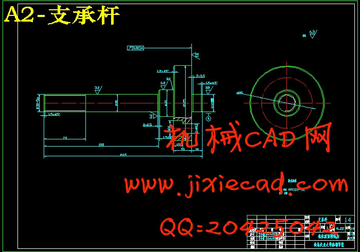
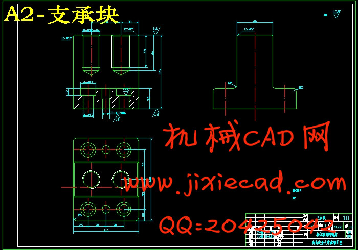
4.1.2定位元件的设计 ………………………………………………………………………………8
4.1.3定位误差的分析和计算 ………………………………………………………………………9
4.2 确定夹紧方案,设计夹紧装置……………………………………………………………………10
4.2.1夹紧力的确定…………………………………………………………………………………10
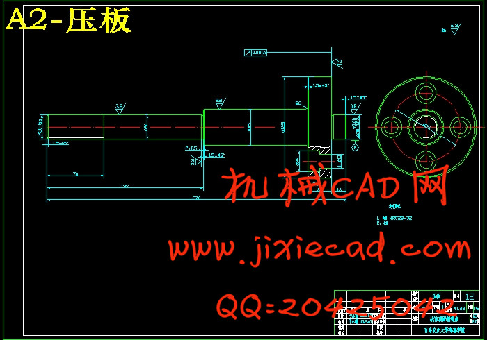
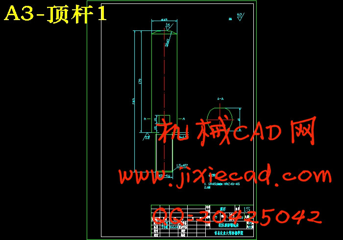
4.2.2夹紧机构的设计………………………………………………………………………………13
4.2.3动力装置(液压油缸)的设计 ……………………………………………………………14
4.3对刀装置的设计 ……………………………………………………………………………………14
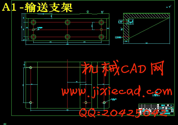
4.4 设计夹具底座………………………………………………………………………………………14
第五章 结论…………………………………………………………………………………16
参考文献 ……………………………………………………………………………………17
致谢 …………………………………………………………………………………………18
附录 …………………………………………………………………………………………19