设计简介
摘要
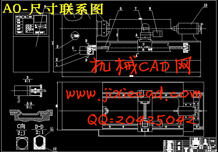
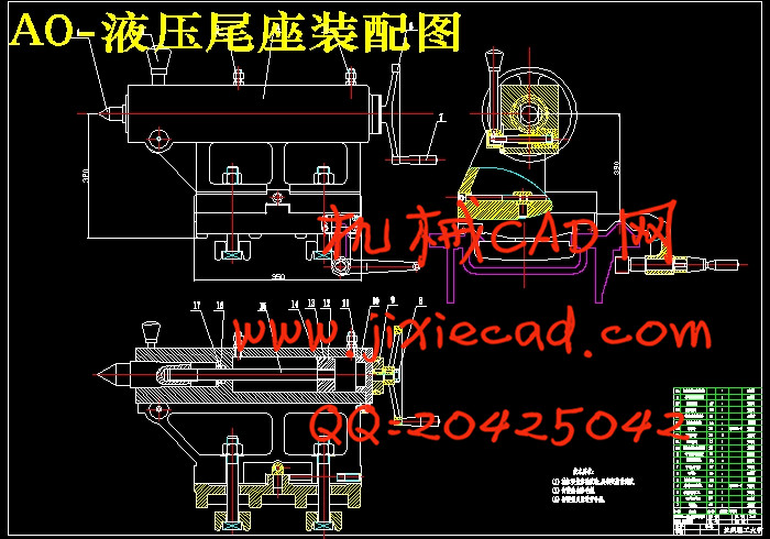
数控机床即数字程序控制机床,是一种自动化机床,数控技术是数控机床研究的核心,是制造业实现自动化、网络化、柔性化、集成化的基础。随着制造技术的发展,现代数控机床借助现代设计技术、工序集约化和新的功能部件使机床的加工范围、动态性能、加工精度和可靠性有了极大的提高。本设计是对Φ630MM数控车床主要进行尾座设计。液压尾座设计的主要内容是尾座体、套筒、顶尖、尾座孔系、尾座导轨,挠度、转角、液压缸内径及压板处螺栓直径、锁紧力的计算及校核。其中选择莫氏4号锥度的尾座顶尖,是利用莫氏锥度自身的结构特性来卡紧尾座顶尖的,它解决了顶尖在工作时会出现松动或转动现象。在套筒中设计了滑键槽和顶尖顶出孔,解决了顶尖在工作时会随套筒转动从而影响工件的加工精度;还在套筒中设计了顶卸的装置,便于顶尖的拆卸。
关键词:数控车床,数控,液压尾座
Abstract
NC machine tool is the digital process control machine tool, is an automated machine tools, CNC technology is the core of numerical control machine tool research, is the manufacturing industry that realizes the automation, network, flexible, integrated foundation. With the development of manufacturing technology, modern CNC machine tools with the aid of the modern design technology, process intensification and the new function part make machine processing range, dynamic performance, the processing precision and reliability are greatly improved.The design of Φ630MM lathe numerical control transformation. Hydraulic tailstock design are the main contents of the tailstock body, sleeve, top, tailstock hole of tailstock guideways, deflection angle,,, inner diameter of the cylinder and the pressure plate, the diameter of the bolt locking force calculation and verification. The choice of Morse No. 4 taper of tailstock center, is the use of Morse taper their structural properties to clamp the tailstock top, which solves the problem of the top in the job will appear when loosening or rotation phenomenon. In the sleeve design of slide key groove and the top spire hole, resolved the top when working with the sleeve to rotate so as to influence the machining precision of the workpiece; still sleeve design top unloading device for removing, top.
Key words: CNC lathe, CNC, hydraulic tailstock
目录
摘 要 IAbstract II
目录 III
第1章 数控机床发展概述 6
1.1数控机床及其特点 6
1.2 数控机床的工艺范围及加工精度 6
1.3 数控机床的经济分析 6
1.4 数控技术的发展趋向 7
1.5 国内外现状 8
1. 6本章小结 9
第2章 总体方案的制定与比较 9
2.1总体方案设计要求 9
2.2 总体方案拟定 10
2.3主要设计内容 11
2.3.1伺服控制系统的选择 11
2.3.2机械部分设计 12
第3章 确定切削用量及选择刀具 13
3.1科学选择数控刀具 13
3.1.1选择数控刀具的原则 13
3.1.2选择数控车削用刀具 14
3.2 设置刀点和换刀点 14
3.3 确定切削用量 15
3.3.1确定主轴转速 15
3.3.2确定进给速度 15
3.3.3 确定背吃刀量 15
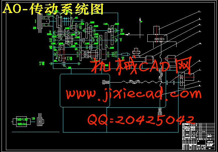
第4章 传动系统图的设计计算 16
4.1 参数的确定 16
4. 2 传动设计 19
4.3转速图的拟定 21
第5章 液压尾座部分设计 24
5.1 液压尾座研究背景和意义 24
5.2液压系统的发展现状 25
5.3 尾座的整体设计 27
第6章 尾座结构计算设计 28
6.1尾座体的设计 28
6.2尾座主轴的设计 29
6.3尾座顶尖的设计 29
6.4螺塞缸的设计 30
6.5尾座导轨的设计 30
6.6尾座孔系设计 31
6.7.1主轴孔的设计 31
6.7.2孔和键的设计 31
6.7.3配合 32
6.7.4密封及偏心轴的设计 33
6.7挠度、转角、锁紧力的计算及校核 33
6.7.1挠度的计算 34
6.7.2转角的计算 34
6.7.3压板处螺栓的选择及校核 34
第7章 数控硬件电路设计 35
7.1硬件电路设计 36
7.1.1 数控系统的硬件结构 36
7.1.2 数控系统硬件电路的功能 36
7.2关于各线路元件之间线路连接 37
7.3关于电路原理图的一些说明 38
总结与展望 40
参考文献 42
致 谢 43