设计简介
摘 要
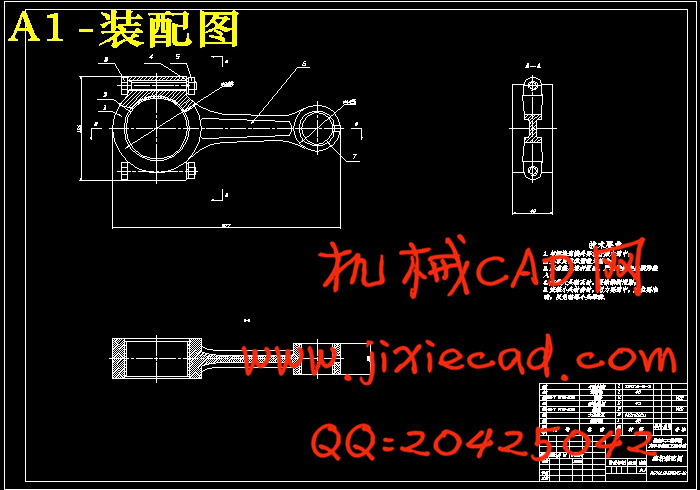
本文以4110柴油机的相关参数作为参考,对四缸柴油机的连杆进行了结构设计和尺寸计算,并对连杆进行了运动学和动力学的理论分析,最后运用Pro/E进行三维建模运用ANSYS进行了有限元分析。
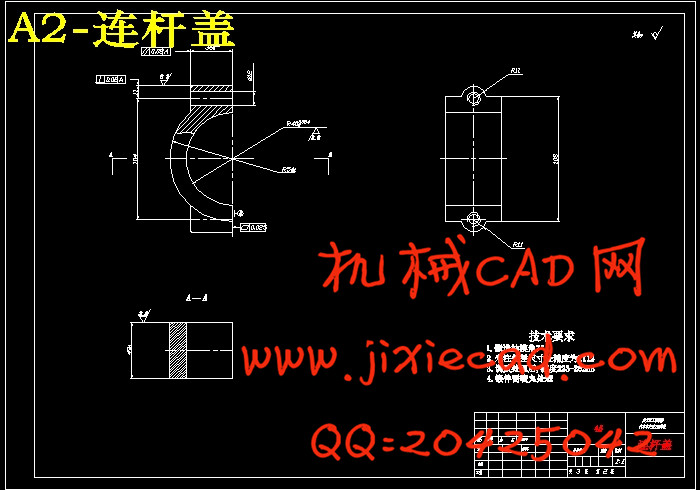
首先,以运动学和动力学的理论知识为依据,对连杆的运动规律以及在运动中的受力等问题进行详尽的分析,并得到了精确的分析结果,同时对连杆用材料进行了比较与分析。其次分别对连杆大头、连杆杆身以及连杆小头进行结构设计及尺寸计算,并进行了结构强度和刚度的校核。再次,应用CAD软件:Pro/E软件建立了连杆的三维几何模型,在此工作的基础上,又对静力作用下对连杆的两种特殊工况;拉伸、压缩工况下进行了受力计算,再将连杆三维几何模型导入ANSYS中对其进行了定义特性、网格划分、施加约束和载荷,最后进行计算以达到对连杆进行强度校核的目的。
关键词:柴油机;连杆;强度校核;Pro/E;ANSYS
ABSTRACT
Taking 4110 as the reference parameters of the diesel engine, four-cylinder diesel e-
ngine connecting rod on the design and size were calculated, and linkage to the theory of kinematics and dynamics analysis, and finally the use of Pro / E for the use of three-dim-
ensional modeling ANSYS finite element analysis carried out.
First, the theoretical knowledge of kinematics and dynamics based on the movement
of connecting rod and the force in motion a detailed analysis of such issues and get accurate results, while the materials were used on the rod comparison and analysis. Followed by on the connecting rod, connecting rod shaft and the connecting rod small end and size of stru-
ctural design calculations, and were checking the structural strength and stiffness. Again, application CAD software: Pro / E software to establish a link of three-dimensional geome-
tric model, based on the work in this, but also on the static on the link under the two special conditions; tension, compression conditions were the force calculation, and then link into ANSYS three-dimensional geometric model is defined in its properties, meshing, impose constraints and loads, and finally calculated to achieve the purpose of checking the strength rod
Key words: Diesel engine;Connecting rod;Strength check;Pro/E;ANSYS
目 录
摘要 Ⅰ
Abstract Ⅱ
第1章 绪 论 1
1.1 选题的目的和意义 1
1.2 国内外的研究现状 2
1.3设计研究的主要内容 4
第2章 连杆的结构设计与分析 5
2.1 连杆的运动和受力分析 5
2.2 连杆的结构分析 5
2.3 连杆的工作条件和设计要点 6
2.4 连杆的材料性能及特点 6
2.5 连杆基本参数的确定 7
2.6 连杆小头的结构设计 8
2.6.1 小头结构型式 8
2.6.2连杆衬套 8
2.6.3小头结构尺寸 9
2.7连杆杆身的结构设计 9
2.7.1杆身结构型式 9
2.7.2杆身结构尺寸 9
2.8 连杆大头的结构设计 10
2.8.1 大头结构型式 10
2.8.2大头结构尺寸 10
2.9 连杆螺栓的设计 10
2.10 本章小结 11
第3章 连杆的强度、刚度计算 12
3.1连杆小头的强度校核 12
3.2连杆小头的刚度计算 14
3.3连杆杆身的强度校核 14
3.4连杆大头的强度校核 17
3.5连杆螺栓的工作负荷与预紧力 18
3.6连杆螺栓的屈服强度校核和疲劳计算 19
3.7本章小结 19
第4章 连杆三维模型的建立及有限元分析 20
4.1 建立连杆大小头及杆身 20
4.1.1建立新文件 20
4.1.2建立连杆体主体 20
4.1.3建立连杆大头和小头 21
4.1.4建立小头油孔 21
4.1.5建立连杆凹槽 22
4.1.6 建立连杆大头部位凸台 22
4.1.7建立螺栓孔 23
4.2建立连杆端盖 23
4.3建立连杆螺栓 24
5.4建立轴瓦及衬套 24
4.5连杆工况选择与载荷计算 25
4.5.1 计算工况的选择 25
4.5.2 连杆载荷的计算 25
4.6连杆几何模型的建立 27
4.7约束条件 29
4.8 连杆应力分析 29
4.8.1连杆拉伸工况下的应力分析 29
4.8.2连杆压缩工况下的应力分析 34
4.9连杆安全系数计算 39
4.10 本章小结 40
结 论 41
参考文献 42
致 谢 43
附 录 44