设计简介
摘要
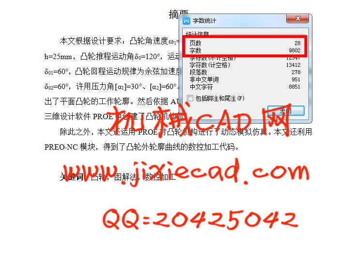
本文根据设计要求:凸轮角速度ω1=1rad/s,逆时针转向,推杆最大行程h=25mm,凸轮推程运动角δ0=120°,运动规律为正弦加速度运动,远休止角δ01=60°,凸轮回程运动规律为余弦加速度运动,回程运动角度δ=120°,近休止角δ02=60°,许用压力角[α1]=30°、[α2]=60°。使用AUTOCAD软件运用图解法设计出了平面凸轮的工作轮廓。然后依据AUTOCAD软件绘制的凸轮外轮廓曲线在三维设计软件PROE中创建了凸轮机构的三维模型。
除此之外,本文还运用PROE对凸轮机构进行了动态模拟仿真。本文还利用PREO-NC模块,得到了凸轮外轮廓曲线的数控加工代码。
关键词:凸轮,图解法,数控加工
Abstract
Based on the design requirements: cam angular velocity ω1 = 1rad / s, CCW, putting stroke h = 25mm, Cam-drive sports angle δ0 = 120 °, the movement of sinusoidal acceleration motion, far angle of repose δ01 = 60 °, the return movement of the cam cosine acceleration motion, the return movement angle δ = 120 °, near the angle of repose δ02 = 60 °, the allowable pressure angle [α1] = 30 °, [α2] = 60 °. Using AUTOCAD software to design a work profile plane cam use graphical method. Then based on the cam curve AUTOCAD software to draw the outline of a three-dimensional model created in three-dimensional design of the cam mechanism in PROE software.
In addition, the paper also carried out using a cam mechanism PROE for dynamic simulation. This paper also uses PREO-NC modules, get the outer contour of the cam curve NC code.
Keywords: Cam, graphical method, CNC machining
目录
摘要 1
Abstract 2
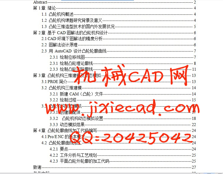
第1章 绪论 4
1.1 凸轮机构概述 4
1.2 凸轮机构课题研究背景及意义 4
1.3 凸轮三维造型技术的国内外发展状况 5
第2章 基于CAD图解法的凸轮机构设计 6
2.1 CAD环境下图解法的精度分析 6
2.2 图解法设计原理 6
2.3 用 AutoCAD 设计凸轮轮廓曲线 7
2.3.1 绘制位移线图 7
2.3.1 绘制凸轮理论廓线 8
2.3.3 绘制凸轮实际廓线 11
第3章 凸轮机构三维建模及动态模拟 13
3.1 PROE简介 13
3.2 凸轮机构三维建模 14
3.2.1 新建CAM(凸轮)文件 14
3.2.2 绘制过程 15
3.3 凸轮机构动态模拟 17
3.3.1 创建装配体 17
3.3.2 凸轮机构动态模拟设置 18
3.3.3 动态模拟结果 22
第4章 凸轮轮廓曲线加工代码编写 24
4.1 Pro/E NC的基本概念 24
4.2 凸轮轮廓曲线加工 24
4.2.1 要点 24
4.2.2 工件分析与工艺规划 25
4.2.3 平面凸轮外轮廓的加工代码 25
致谢 27
参考文献 28
本文根据设计要求:凸轮角速度ω1=1rad/s,逆时针转向,推杆最大行程h=25mm,凸轮推程运动角δ0=120°,运动规律为正弦加速度运动,远休止角δ01=60°,凸轮回程运动规律为余弦加速度运动,回程运动角度δ=120°,近休止角δ02=60°,许用压力角[α1]=30°、[α2]=60°。使用AUTOCAD软件运用图解法设计出了平面凸轮的工作轮廓。然后依据AUTOCAD软件绘制的凸轮外轮廓曲线在三维设计软件PROE中创建了凸轮机构的三维模型。
除此之外,本文还运用PROE对凸轮机构进行了动态模拟仿真。本文还利用PREO-NC模块,得到了凸轮外轮廓曲线的数控加工代码。
关键词:凸轮,图解法,数控加工
Abstract
Based on the design requirements: cam angular velocity ω1 = 1rad / s, CCW, putting stroke h = 25mm, Cam-drive sports angle δ0 = 120 °, the movement of sinusoidal acceleration motion, far angle of repose δ01 = 60 °, the return movement of the cam cosine acceleration motion, the return movement angle δ = 120 °, near the angle of repose δ02 = 60 °, the allowable pressure angle [α1] = 30 °, [α2] = 60 °. Using AUTOCAD software to design a work profile plane cam use graphical method. Then based on the cam curve AUTOCAD software to draw the outline of a three-dimensional model created in three-dimensional design of the cam mechanism in PROE software.
In addition, the paper also carried out using a cam mechanism PROE for dynamic simulation. This paper also uses PREO-NC modules, get the outer contour of the cam curve NC code.
Keywords: Cam, graphical method, CNC machining
目录
摘要 1
Abstract 2
第1章 绪论 4
1.1 凸轮机构概述 4
1.2 凸轮机构课题研究背景及意义 4
1.3 凸轮三维造型技术的国内外发展状况 5
第2章 基于CAD图解法的凸轮机构设计 6
2.1 CAD环境下图解法的精度分析 6
2.2 图解法设计原理 6
2.3 用 AutoCAD 设计凸轮轮廓曲线 7
2.3.1 绘制位移线图 7
2.3.1 绘制凸轮理论廓线 8
2.3.3 绘制凸轮实际廓线 11
第3章 凸轮机构三维建模及动态模拟 13
3.1 PROE简介 13
3.2 凸轮机构三维建模 14
3.2.1 新建CAM(凸轮)文件 14
3.2.2 绘制过程 15
3.3 凸轮机构动态模拟 17
3.3.1 创建装配体 17
3.3.2 凸轮机构动态模拟设置 18
3.3.3 动态模拟结果 22
第4章 凸轮轮廓曲线加工代码编写 24
4.1 Pro/E NC的基本概念 24
4.2 凸轮轮廓曲线加工 24
4.2.1 要点 24
4.2.2 工件分析与工艺规划 25
4.2.3 平面凸轮外轮廓的加工代码 25
致谢 27
参考文献 28