设计简介
4缸发动机油底壳组合钻床Ⅱ主轴箱设计
摘 要
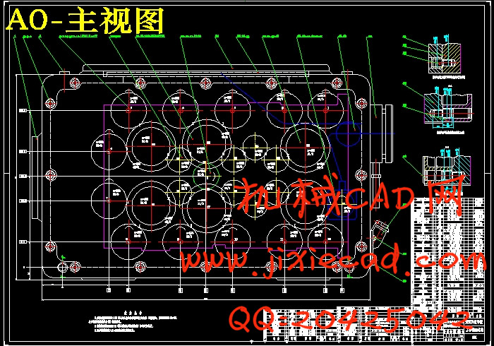
本次设计是在了解4缸发动机油底壳的基本结构,组合机床的基本配置方式、工艺范围、加工精度、经济分析及发展趋势以及组合机床各通用部件的功能及特点的基础上,进行的组合机床总体设计和主轴箱设计。本次设计的机床用来进行油底壳底面的12个孔加工。
本设计的前期具体工作是分析影响组合机床方案制定的主要因素,制定工艺,确定机床配置形式及结构方案,选择切削用量三要素,选择刀具,确定切削力、切削扭矩、切削功率、刀具耐用度。中期的具体工作是了解通用主轴箱的组成,在前期工作的基础上绘制主轴箱设计的原始依据图,选择主轴结构型式,进行动力计算,设计传动方案并计算主轴箱的主轴坐标及确定传动零件的尺寸。后期主要工作是在传动方案确定之后,对传功方案里的传动系统进行校核,主要包括对齿轮模数的校核和轴的校核。在满足生产各方面要求的前提下,绘制轴向装配总图及主轴箱局部剖试图。
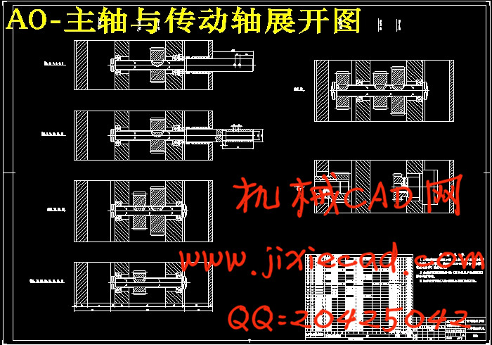
主轴箱传动方案为:驱动轴0轴通过17和22号轴上的第3排齿轮带动中间传动轴17和22号轴,传动比为0.67。17和22号轴上有3排齿轮,第一排齿轮带动3、4、9、10号主轴,第二排齿轮带动16、18、21、23号传动轴。18和21号传动轴通过19和20号传动轴上的第二排齿轮带动19和20号传动轴。19和20号传动轴通过第一排齿轮传递给5、6、7、8、9号主轴。16和23号传动轴分别通过15、14号传动轴和24、25号传动轴带动13和26号传动轴上的第二排齿轮。13和26号轴通过13和26号轴上的第一排齿轮传递给1、2、11、12号主轴。
关键词:组合机床,主轴箱,孔加工,传动方案
4-cylinder engine sump Combination Drilling II spindle box design
Author: Li zhenting
Tutor : Jia baihe
Abstract
This design is to understand the basic structure of the 4-cylinder engine oil pan, the basic configuration of the machine tool, the range of technology, precision machining, economic analysis and development trends, as well as the general components of thecombination of machine functions and characteristics on the basis of conducted designof the overall machine tool design and the spindle box. The design of the machine used for the sump bottom surface 12 of hole machining.
The early stage of this design work is to analyze the main factors of the combination ofmachine tool programming, to develop technology to determine machine configuration in the form and structure of programs, select the three elements of the cutting parameters,select the tool to determine the cutting force, cutting torque, cutting power, tool lifedegrees. The medium-term work is to understand the composition of the commonspindle box drawn in the preliminary work on the basis of the original basis of the spindle box diagram, select the spindle structure type, dynamic calculation, the design of thetransmission scheme and the calculation of the coordinates of the headstock spindle andto determine the transmission parts size. The main work of the late in the transmissionscheme for the drive system transfer power scheme checking, including the modulus ofgear check and check. Meet the production requirements of the various aspects of the premise, draw axial assembly of the General Plan and spindle box breakout attempt to.
Transmission scheme of spindle box: 0-axis drive shaft gear driven axis by 17 and 22,three rows of the intermediate transmission shaft 17 and No. 22 shaft, three rows of geartransmission ratio 0.67, 17 and 22 axis, the first The row of gear drive 3,4,9,10 number ofspindles, the second row of gear driven 16,18,21,23 number of drive shaft. 18 and 21 onthe drive shaft 19 and on the 20th of the second row of the gear driven drive shaft through the drive shaft 19 and on the 20th. Pass the first row of gears 19 and 20 No. drive shaft tothe 5,6,7,8,9 No. spindle. 16 and 23 respectively driven by the drive shaft drive shaft and24, 25 15:14 No. 13 and No. 26 on the second row of the gear drive shaft drive shaft. 13and 26 axis through the first row of the gear shaft 13 and on the 26th passed to 1,2,11,12No. spindle.
Keywords: machine tool, spindle box, hole processing, transmission scheme
目 录
前 言 I
摘 要 II
1 绪论 1
1.1组合机床的型式及其特点 1
1.2组合机床工艺范围及加工精度 2
1.2.1组合机床的工艺范围 2
1.2.2组合机床的加工精度 2
1.3采用组合机床的经济分析 3
1.4组合机床的发展趋势 4
1.4.1提高通用部件的水平 4
1.4.2发展适应中、小批生产的组合机床 4
1.4.3采用新刀具 4
1.4.4发展自动监测技术 5
1.4.5扩大工艺范围 5
2 组合机床总体设计 6
2.1组合机床的方案设计 6
2.1.1拟定方案阶段 6
2.1.2技术设计阶段 6
2.1.3工作设计阶段 6
2.2零件分析 6
2.2.1 4缸发动机油底壳的功用和结构特点 6
2.2.2基准的选择 7
2.2.3加工阶段的划分 7
3 绘制“三图一卡” 9
3.1加工工序图 9
3.1.1被加工零件工序图的作用和要求 9
3.1.2被加工零件工序图的内容 9
3.1.3编制被加工零件工序图的注意事项 9
3.2加工示意图 10
3.2.1被加工零件示意图的作用 10
3.2.2被加工零件示意图的内容 10
3.2.3选择刀具、工具及导向装置 10
3.2.4确定动力部件的工作循环及工作行程 14
3.2.5其它应注意的问题 14
3.2.6加工示意图简图 15
3.3机床联系尺寸图 15
3.3.1被加工零件联系尺寸图的作用 15
3.3.2被加工零件联系尺寸图的内容 16
3.3.3动力部件的选择 16
3.3.4组合机床其它尺寸的确定 17
4 多轴箱——主轴箱设计 18
4.1 多轴箱的基本结构 18
4.2通用多轴箱设计 18
4.2.1绘制多轴箱设计原始依据图 19
4.2.2主轴、齿轮的确定及动力运算 20
4.2.3多轴箱传动设计 23
4.2.4多轴箱坐标计算、绘制坐标检查图 26
4.3多轴箱的传动设计方案 29
4.3.1传动设计方案分析 29
4.3.2传动系统的设计计算 29
4.3.3传动系统的校核计算 34
4.4 绘制多轴箱总图及零件图 41
4.4.1多轴箱总图设计 41
4.4.2多轴箱零件设计 42
结 论 43
致 谢 44
参考文献 45
摘 要
本次设计是在了解4缸发动机油底壳的基本结构,组合机床的基本配置方式、工艺范围、加工精度、经济分析及发展趋势以及组合机床各通用部件的功能及特点的基础上,进行的组合机床总体设计和主轴箱设计。本次设计的机床用来进行油底壳底面的12个孔加工。
本设计的前期具体工作是分析影响组合机床方案制定的主要因素,制定工艺,确定机床配置形式及结构方案,选择切削用量三要素,选择刀具,确定切削力、切削扭矩、切削功率、刀具耐用度。中期的具体工作是了解通用主轴箱的组成,在前期工作的基础上绘制主轴箱设计的原始依据图,选择主轴结构型式,进行动力计算,设计传动方案并计算主轴箱的主轴坐标及确定传动零件的尺寸。后期主要工作是在传动方案确定之后,对传功方案里的传动系统进行校核,主要包括对齿轮模数的校核和轴的校核。在满足生产各方面要求的前提下,绘制轴向装配总图及主轴箱局部剖试图。
主轴箱传动方案为:驱动轴0轴通过17和22号轴上的第3排齿轮带动中间传动轴17和22号轴,传动比为0.67。17和22号轴上有3排齿轮,第一排齿轮带动3、4、9、10号主轴,第二排齿轮带动16、18、21、23号传动轴。18和21号传动轴通过19和20号传动轴上的第二排齿轮带动19和20号传动轴。19和20号传动轴通过第一排齿轮传递给5、6、7、8、9号主轴。16和23号传动轴分别通过15、14号传动轴和24、25号传动轴带动13和26号传动轴上的第二排齿轮。13和26号轴通过13和26号轴上的第一排齿轮传递给1、2、11、12号主轴。
关键词:组合机床,主轴箱,孔加工,传动方案
4-cylinder engine sump Combination Drilling II spindle box design
Author: Li zhenting
Tutor : Jia baihe
Abstract
This design is to understand the basic structure of the 4-cylinder engine oil pan, the basic configuration of the machine tool, the range of technology, precision machining, economic analysis and development trends, as well as the general components of thecombination of machine functions and characteristics on the basis of conducted designof the overall machine tool design and the spindle box. The design of the machine used for the sump bottom surface 12 of hole machining.
The early stage of this design work is to analyze the main factors of the combination ofmachine tool programming, to develop technology to determine machine configuration in the form and structure of programs, select the three elements of the cutting parameters,select the tool to determine the cutting force, cutting torque, cutting power, tool lifedegrees. The medium-term work is to understand the composition of the commonspindle box drawn in the preliminary work on the basis of the original basis of the spindle box diagram, select the spindle structure type, dynamic calculation, the design of thetransmission scheme and the calculation of the coordinates of the headstock spindle andto determine the transmission parts size. The main work of the late in the transmissionscheme for the drive system transfer power scheme checking, including the modulus ofgear check and check. Meet the production requirements of the various aspects of the premise, draw axial assembly of the General Plan and spindle box breakout attempt to.
Transmission scheme of spindle box: 0-axis drive shaft gear driven axis by 17 and 22,three rows of the intermediate transmission shaft 17 and No. 22 shaft, three rows of geartransmission ratio 0.67, 17 and 22 axis, the first The row of gear drive 3,4,9,10 number ofspindles, the second row of gear driven 16,18,21,23 number of drive shaft. 18 and 21 onthe drive shaft 19 and on the 20th of the second row of the gear driven drive shaft through the drive shaft 19 and on the 20th. Pass the first row of gears 19 and 20 No. drive shaft tothe 5,6,7,8,9 No. spindle. 16 and 23 respectively driven by the drive shaft drive shaft and24, 25 15:14 No. 13 and No. 26 on the second row of the gear drive shaft drive shaft. 13and 26 axis through the first row of the gear shaft 13 and on the 26th passed to 1,2,11,12No. spindle.
Keywords: machine tool, spindle box, hole processing, transmission scheme
目 录
前 言 I
摘 要 II
1 绪论 1
1.1组合机床的型式及其特点 1
1.2组合机床工艺范围及加工精度 2
1.2.1组合机床的工艺范围 2
1.2.2组合机床的加工精度 2
1.3采用组合机床的经济分析 3
1.4组合机床的发展趋势 4
1.4.1提高通用部件的水平 4
1.4.2发展适应中、小批生产的组合机床 4
1.4.3采用新刀具 4
1.4.4发展自动监测技术 5
1.4.5扩大工艺范围 5
2 组合机床总体设计 6
2.1组合机床的方案设计 6
2.1.1拟定方案阶段 6
2.1.2技术设计阶段 6
2.1.3工作设计阶段 6
2.2零件分析 6
2.2.1 4缸发动机油底壳的功用和结构特点 6
2.2.2基准的选择 7
2.2.3加工阶段的划分 7
3 绘制“三图一卡” 9
3.1加工工序图 9
3.1.1被加工零件工序图的作用和要求 9
3.1.2被加工零件工序图的内容 9
3.1.3编制被加工零件工序图的注意事项 9
3.2加工示意图 10
3.2.1被加工零件示意图的作用 10
3.2.2被加工零件示意图的内容 10
3.2.3选择刀具、工具及导向装置 10
3.2.4确定动力部件的工作循环及工作行程 14
3.2.5其它应注意的问题 14
3.2.6加工示意图简图 15
3.3机床联系尺寸图 15
3.3.1被加工零件联系尺寸图的作用 15
3.3.2被加工零件联系尺寸图的内容 16
3.3.3动力部件的选择 16
3.3.4组合机床其它尺寸的确定 17
4 多轴箱——主轴箱设计 18
4.1 多轴箱的基本结构 18
4.2通用多轴箱设计 18
4.2.1绘制多轴箱设计原始依据图 19
4.2.2主轴、齿轮的确定及动力运算 20
4.2.3多轴箱传动设计 23
4.2.4多轴箱坐标计算、绘制坐标检查图 26
4.3多轴箱的传动设计方案 29
4.3.1传动设计方案分析 29
4.3.2传动系统的设计计算 29
4.3.3传动系统的校核计算 34
4.4 绘制多轴箱总图及零件图 41
4.4.1多轴箱总图设计 41
4.4.2多轴箱零件设计 42
结 论 43
致 谢 44
参考文献 45