设计简介
摘 要
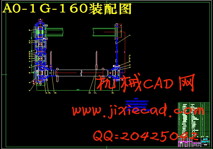
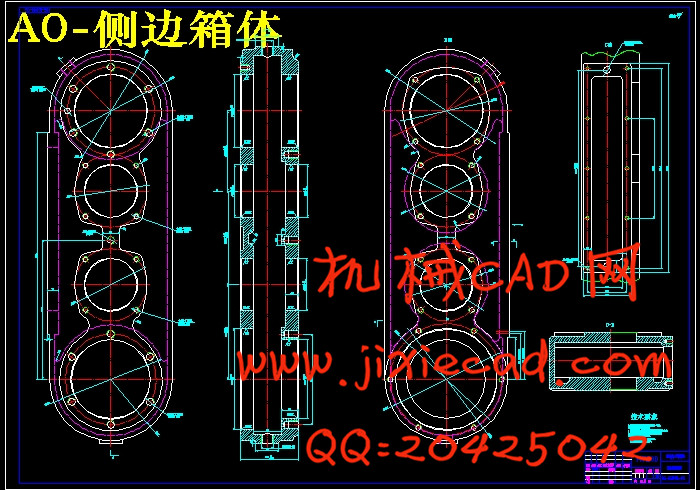
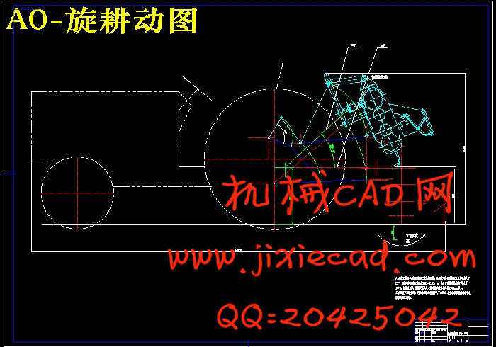
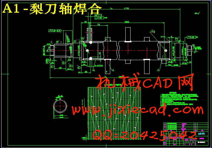
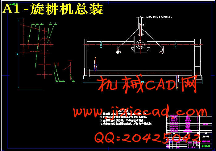
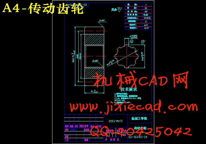
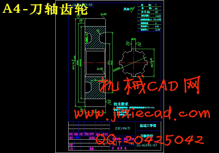
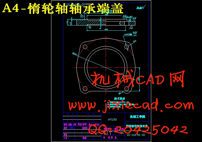
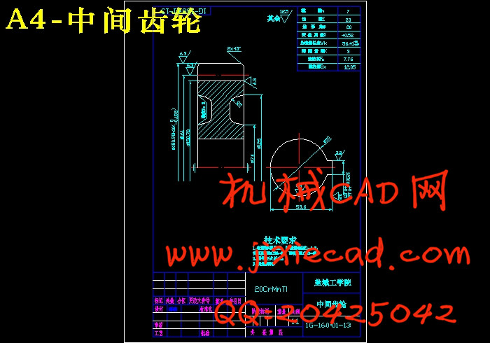
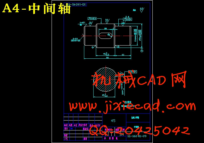
设计课题为1G-160型旋耕灭茬机总体及侧边传动装置设计,来源于生产实际。本设计主要是在普通卧式旋耕机的基础上改进设计,使之既能旋耕又能灭荐,以实现一机多用。设计的主要内容为:总体方案设计、绘制灭茬状态工作总图,设计侧边或中间齿轮传动装置及刀辊轴。
通过改进设计,增加刀辊轴的转速和转向。在工作时,通过适当的拆卸和改装,就可实现不同功能的作业,以达到一机多能的目的。
本课题的实现解决了现有旋耕机只能旋耕不能灭茬而灭茬机又只能灭茬不能旋耕的问题。本课题新颖实用,技术上有较大改进,具有很大的市场前景。
关键词:旋耕灭茬机;侧边传动装置;刀辊轴。
The rotary tillage stubble cleaner of Model 1G-160 is overall and the transmission device is designed by the side
Abstract :Design subject rotary tillage stubble cleaner overall for Model 1G-160 and transmission device design by the side, stem from production reality. Is it is it design to improve on the basis of ordinary horizontal rotary tillage machine mainly to design originally, make their can rotary tillage can is it recommend to kill also , in order to realize one machine multi-purpose. The main content designed is: Overall conceptual design , drawing the state job general drawing of the stubble-cleaning , designing by the side or middle gear system and one one hundred sheets of rollers axle .
Design through improving, increase the rotational speed of the axle of one one hundred sheets of rollers and change direction. While working, through proper dismantlement and repacking , can realize the homework of different functions , in order to be up to a machine multi-functional purpose .
Can can only solve rotary tillage not existing of rotary tillage of stubble-cleaning of realizations of subject but stubble cleaner can only stubble-cleaning can problem of rotary tillage. This subject is novel and practical, there is greater improvement technically , have very great market prospects.
Keywords: Rotary tillage stubble cleaner ; Transmission device by the side; Axle of one one hundred sheets of rollers.
目 录
1前言…………………………………………………………………………………1
2 方案的拟定…………………………………………………………………………4
1.1 设计参数要求……………………………………………………………………5
1.2 方案的选择………………………………………………………………………5
1.2.1方案1……………………………………………………………………………6
1.2.2方案2………………………………………………………………………… 7
1.2.3方案3………………………………………………………………………… 7
1.3 方案对比分析……………………………………………………………………7
3运动计算……………………………………………………………………………8
4 动力计算………………………………………………………………………… 9
4.1 各传动副效率………………………………………………………………… 10
4.2 动力分配……………………………………………………………………… 10
4.2.1拖拉机动力输出轴的额定输出功率…………………………………………10
4.2.2第一轴及小锥齿轮Z动率,转速和扭矩…………………………………… 11
4.2.3大锥齿轮Z2的功率轨迹的扭矩为:………………………………………… 11
4.2.4第二轴功率轨迹和扭矩为:………………………………………………… 11
4.2.5第二轴Z3齿轮功率、转速和扭矩为:………………………………………11
4.2.6第Ⅲ轴Z4齿轮功率……………………………………………………………11
4.2.7第Ⅲ轴(随轮轴)不传递扭矩,故不校核:…………………………………11
4.2.8第Ⅳ轴Z5齿轮功率……………………………………………………………11
4.2.9第Ⅳ轴(随轮轴)的传递扭矩,故不校核………………………………… 11
4.2.10刀轴Z6齿轮功率、转速和扭矩………………………………………………11
4.2.11刀轴功率,转速和扭矩………………………………………………………11
5主要零件的强度校核工………………………………………………………… 12
5.1 圆柱齿轮的计算……………………………………………………………… 12
5.1.1齿轮的材料、精度和齿数选择………………………………………………12
5.1.2设计计算………………………………………………………………………13
5.1.3第一对直齿圆柱齿轮主要尺寸的计算………………………………………13
5.1.4第二对直齿圆柱齿轮的主要参数的计算……………………………………14
5.2 轴的选择……………………………………………………………………… 17
5.3 轴承的选择…………………………………………………………………… 17
6尺寸链计算……………………………………………………………………… 17
参考文献…………………………………………………………………………… 18
致谢…………………………………………………………………………………19
结论…………………………………………………………………………………20
附图清单……………………………………………………………………………21