设计简介
摘要
在汽车零配件加工生产的过程中,如果使用人工上下料,则其不仅劳动强度大,而
且效率低,工作环境也较差,有诸多不足。而使用自动上下料装置,则具有传送快速、
定位精度高以及可以长时间连续作业,大大提高了生产效率。
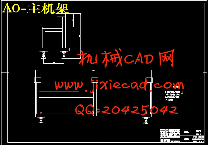
本文拟设计一个适合于发动机配件生产线自动上料系统,该系统主要包括链传动系
统和偏置曲柄滑块推杆机构两个部分。
在链传动系统中,选用合适的三相异步电机和与之匹配的减速器,再选择合适的间
歇分割器,实现间歇传动,再通过一组链传动,从而实现预定减速。链传送带上的链条
选择带翼的 08B链条,翼上可以安装托盘,托盘上放置运输件,当链条转动时可以实现
运输上料,链传送带上有张装置,可以保证从动链轮与主动轮在同一水平线上,且能保
证链条的张紧。
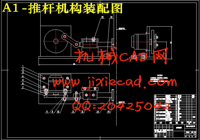
在偏置曲柄滑块推杆结构中,在推杆位置末端放置接近开关传感器,当输送件到达
指定位置时,接近开关感应输出信号给予步进电机信号,步进电机转动,带动设计的偏
置曲柄滑块机构实现直线运动,完成推杆动作。设计的链传动与推杆形成配合完成自动
上料系统。
关键词:发动机配件:自动上料:间歇:链传动;偏置曲柄滑块机构;
I
Abstract
In the process of automotive parts production,If you use the manual loading,then
it is not only a Labor-intensive,but also inefficiencies,and the working environment is poor ,
there are many deficiencies.However, the use of automatic loading and unloading devices,
with transfer speed, high precision and long-time continuous operation, greatly improving
production efficiency.
This paper intends to design a suitable engine parts production line automatic
feeding systems. The system consists of two parts chain drive and the putt of offset crank
slider mechanism.
In the chain of transmission system,, choice the appropriate of three-phase asynchronous
motors and matching reducer. Then select the appropriate intermittent segmentation to
achieve intermittent drive, and then achieve a predetermined deceleration through a set of
chain drive. Chain links on the conveyor belt will select the chain links of winged 08B, the
wing may be mounted the tray. The tray is placed on the transport pieces. When the chain
rotating , transporting the material can be achieved. There tensioning device on the conveyor
of chain can ensure driven sprocket and active wheel at the same level, and can ensure that the
chain tension .
In the the putt of offset crank slider mechanism,at the end of the push rod position,
the sensor is placed close to the switch. When transporting pieces arrived at the designated
location, proximity switch sensor output signal that is given to the stepper motor, the stepper
motor rotating, and offset slider-crank mechanism drives by the design of linear motion. Then
pushing rod action is completed . The chain drive and putting of designed form with the
completion of automatic feeding systems.
Keywords:Engine parts: Automatic feeding: Intermittent: Chain drive; Bias slider-crank
mechanism;putter
II
目录............................................................................................................................. III
1
引言.......................................................................................................................... 1
1.1自动送料机构的背景与发展前景..................................................................... 1
总体方案设计.......................................................................................................... 3
2.1课题设计方案对比............................................................................................ 3
2..1.1方案一................................................................................................... 3
2.1.2方案二..................................................................................................... 4
2.1.3方案三..................................................................................................... 5
2.2总方案结构设计思路......................................................................................... 6
3.机械元件的选择与设计计算..................................................................................... 7
3.1链传动系统设计................................................................................................. 7
3.1.1链条的选择.............................................................................................. 7
3.1.2链轮的设计与计算................................................................................ 10
3.1.3链轮的连接与装配............................................................................... 14
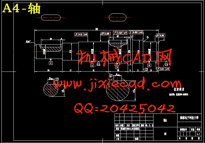
3.1.4轴的校核.............................................................................................. 15
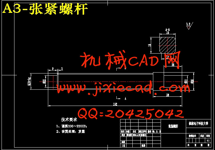
3.1.5链轮张紧装置的设计........................................................................... 16
3.1.6链传送带框架设计................................................................................ 16
3.1.7托盘设计.............................................................................................. 17
3.1.8顶梁杆设计........................................................................................... 18
3.1.9调节杆设计........................................................................................... 18
3.1.10支撑钢板设计..................................................................................... 19
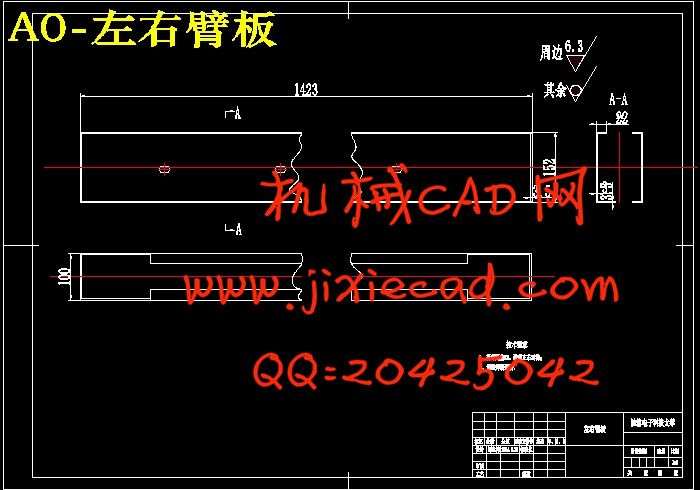
3.1.11臂板设计............................................................................................ 20
3.2推杆的设计与计算........................................................................................... 20
3.2.1推杆行程计算...................................................................................... 21
3.2.2曲柄连杆的设计.................................................................................. 21
3.2.3垫片设计............................................................................................... 22
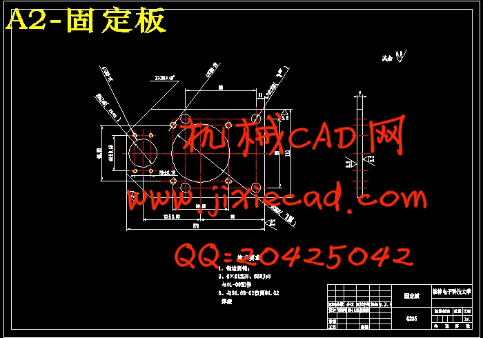
3.2.4转盘以及固定钢板设计...................................................................... 22
3.2.5直线轴承的设计选择.......................................................................... 23
3.2.6推杆末端组合件设计.......................................................................... 24
4电气元件的选择计算................................................................................................ 26
4.1用于链传动的电动机的计算与选择............................................................... 26
4.1.1链传动台的摩擦力的计算.................................................................... 26
4.1.2扭矩、功率、减速比的计算以及电机的选择.................................. 27
4.2推杆的电动机的计算与选择........................................................................... 28
总结.......................................................................................................................... 30
5
谢辞.............................................................................................................................. 31
参考文献.......................................................................................................................... 33
在汽车零配件加工生产的过程中,如果使用人工上下料,则其不仅劳动强度大,而
且效率低,工作环境也较差,有诸多不足。而使用自动上下料装置,则具有传送快速、
定位精度高以及可以长时间连续作业,大大提高了生产效率。
本文拟设计一个适合于发动机配件生产线自动上料系统,该系统主要包括链传动系
统和偏置曲柄滑块推杆机构两个部分。
在链传动系统中,选用合适的三相异步电机和与之匹配的减速器,再选择合适的间
歇分割器,实现间歇传动,再通过一组链传动,从而实现预定减速。链传送带上的链条
选择带翼的 08B链条,翼上可以安装托盘,托盘上放置运输件,当链条转动时可以实现
运输上料,链传送带上有张装置,可以保证从动链轮与主动轮在同一水平线上,且能保
证链条的张紧。
在偏置曲柄滑块推杆结构中,在推杆位置末端放置接近开关传感器,当输送件到达
指定位置时,接近开关感应输出信号给予步进电机信号,步进电机转动,带动设计的偏
置曲柄滑块机构实现直线运动,完成推杆动作。设计的链传动与推杆形成配合完成自动
上料系统。
关键词:发动机配件:自动上料:间歇:链传动;偏置曲柄滑块机构;
I
Abstract
In the process of automotive parts production,If you use the manual loading,then
it is not only a Labor-intensive,but also inefficiencies,and the working environment is poor ,
there are many deficiencies.However, the use of automatic loading and unloading devices,
with transfer speed, high precision and long-time continuous operation, greatly improving
production efficiency.
This paper intends to design a suitable engine parts production line automatic
feeding systems. The system consists of two parts chain drive and the putt of offset crank
slider mechanism.
In the chain of transmission system,, choice the appropriate of three-phase asynchronous
motors and matching reducer. Then select the appropriate intermittent segmentation to
achieve intermittent drive, and then achieve a predetermined deceleration through a set of
chain drive. Chain links on the conveyor belt will select the chain links of winged 08B, the
wing may be mounted the tray. The tray is placed on the transport pieces. When the chain
rotating , transporting the material can be achieved. There tensioning device on the conveyor
of chain can ensure driven sprocket and active wheel at the same level, and can ensure that the
chain tension .
In the the putt of offset crank slider mechanism,at the end of the push rod position,
the sensor is placed close to the switch. When transporting pieces arrived at the designated
location, proximity switch sensor output signal that is given to the stepper motor, the stepper
motor rotating, and offset slider-crank mechanism drives by the design of linear motion. Then
pushing rod action is completed . The chain drive and putting of designed form with the
completion of automatic feeding systems.
Keywords:Engine parts: Automatic feeding: Intermittent: Chain drive; Bias slider-crank
mechanism;putter
II
目录............................................................................................................................. III
1
引言.......................................................................................................................... 1
1.1自动送料机构的背景与发展前景..................................................................... 1
总体方案设计.......................................................................................................... 3
2.1课题设计方案对比............................................................................................ 3
2..1.1方案一................................................................................................... 3
2.1.2方案二..................................................................................................... 4
2.1.3方案三..................................................................................................... 5
2.2总方案结构设计思路......................................................................................... 6
3.机械元件的选择与设计计算..................................................................................... 7
3.1链传动系统设计................................................................................................. 7
3.1.1链条的选择.............................................................................................. 7
3.1.2链轮的设计与计算................................................................................ 10
3.1.3链轮的连接与装配............................................................................... 14
3.1.4轴的校核.............................................................................................. 15
3.1.5链轮张紧装置的设计........................................................................... 16
3.1.6链传送带框架设计................................................................................ 16
3.1.7托盘设计.............................................................................................. 17
3.1.8顶梁杆设计........................................................................................... 18
3.1.9调节杆设计........................................................................................... 18
3.1.10支撑钢板设计..................................................................................... 19
3.1.11臂板设计............................................................................................ 20
3.2推杆的设计与计算........................................................................................... 20
3.2.1推杆行程计算...................................................................................... 21
3.2.2曲柄连杆的设计.................................................................................. 21
3.2.3垫片设计............................................................................................... 22
3.2.4转盘以及固定钢板设计...................................................................... 22
3.2.5直线轴承的设计选择.......................................................................... 23
3.2.6推杆末端组合件设计.......................................................................... 24
4电气元件的选择计算................................................................................................ 26
4.1用于链传动的电动机的计算与选择............................................................... 26
4.1.1链传动台的摩擦力的计算.................................................................... 26
4.1.2扭矩、功率、减速比的计算以及电机的选择.................................. 27
4.2推杆的电动机的计算与选择........................................................................... 28
总结.......................................................................................................................... 30
5
谢辞.............................................................................................................................. 31
参考文献.......................................................................................................................... 33