设计简介
摘要
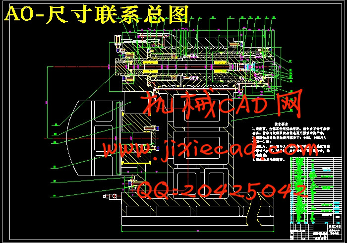
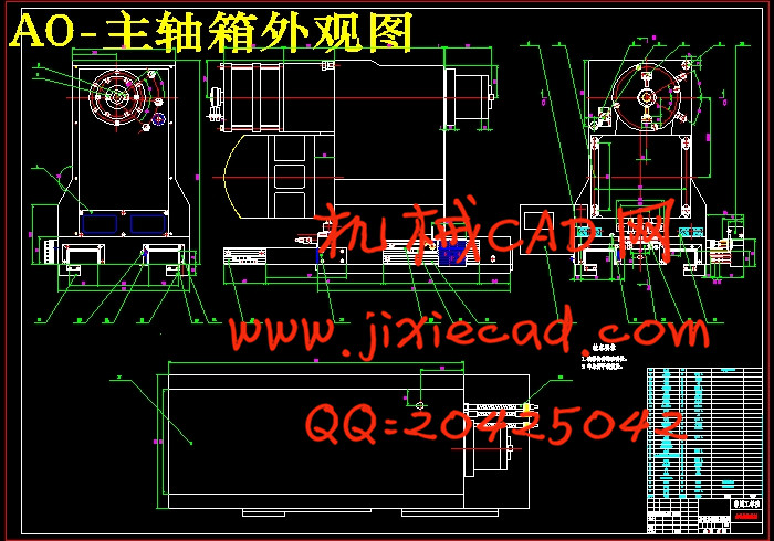
本文介绍了立式加工中心的一些基本概况,简述了机床主传动系统方面的原理和类型,分析了各种传动方案的机理。立式加工中心主传动系统由主轴电动机、主轴传动系统和主轴组件三部分组成。本文详细介绍了立式加工中心主传动系统的设计过程,该立式加工中心选用多楔带传动,该种传动方式的特点在于它能使主传动系统的结构比较简单,而且避免了齿轮传动的振动和噪声。文中介绍了立式加工中心主传动系统各种传动方案优缺点的比较、主传动方案的选择和确定、主传动变速系统的设计计算、主轴组件的设计并确定主轴的卸荷装置和结构形式以及关键零件的校核等设计过程。
关键词:数控机床 立式加工中心 主传动系统 主轴组件 卸荷装置
本文介绍了立式加工中心的一些基本概况,简述了机床主传动系统方面的原理和类型,分析了各种传动方案的机理。立式加工中心主传动系统由主轴电动机、主轴传动系统和主轴组件三部分组成。本文详细介绍了立式加工中心主传动系统的设计过程,该立式加工中心选用多楔带传动,该种传动方式的特点在于它能使主传动系统的结构比较简单,而且避免了齿轮传动的振动和噪声。文中介绍了立式加工中心主传动系统各种传动方案优缺点的比较、主传动方案的选择和确定、主传动变速系统的设计计算、主轴组件的设计并确定主轴的卸荷装置和结构形式以及关键零件的校核等设计过程。
关键词:数控机床 立式加工中心 主传动系统 主轴组件 卸荷装置
Abstract
Some basic concepts and the general knowledge of the vertical machining center were introduced in this paper. The principle and types of the main drive system, analysis mechanism of the transmission project are brief described. The spindle drive system of vertical machining center, including spindle drive motor, transmission and spindle subassembly. The design process of vertical machining center main drive system were introduced in detail in this paper. The vertical machining center used arc tooth timing belt drive, the species transmission features is that it enables the structure of main drive system is relatively simple, and to avoid the noise and vibration. Compared of the program merit and demerit are detailed, the program options and determines of vertical machining center spindle drive system is detailed, main gearshift system and spindle is subassembly designed in this paper.
Key Words: CNC Vertical machining center Main drive system Spindle subassembly Unloading device
目 录
第一章 绪论 …………………………………………………………………………… 1
1.1、引言 ………………………………………………………………………1
1.2、数控机床的基本概况 ………………………………………………………………1
1.3、加工中心的基本概念和分类 ………………………………………………………2
1.4、加工中心的结构组成 ………………………………………………………………3
1.5、加工中心的发展趋势 ………………………………………………………………3
第二章 加工中心主传动系统方案的确定 …………………………………………5
2.1 加工中心主传动系统简介 ………………………………………………………5
2.2 对加工中心主传动系统的要求 …………………………………………………5
2.3 主传动的类型及方案选择 ………………………………………………………6
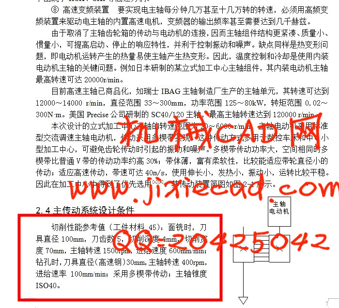
2.4 主传动系统设计条件 ………………………………………………………… 7
第三章 主传动变速系统主要参数计算 ………………………………………… 8
3.1 计算切削功率 ………………………………………………………………… 8
3.2 计算主传动功率 ……………………………………………………………… 8
3.3 确定电动机型号 ……………………………………………………………… 9
3.4多楔带传动的计算 ………………………………………………………………… 9
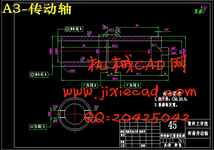
3.5 主轴的卸荷装置……………………………………………………………………11
3.5.1 径向力的卸荷………………………………………………………………12
3.5.2 轴向力的卸荷………………………………………………………………13
第四章 主轴组件设计 ……………………………………………………… 14
4.1 主轴组件的设计要求和步骤 ………………………………………………… 14
4.1.1 主轴组件的设计要求 ………………………………………………… 14
4.1.2 主轴组件的设计步骤 ………………………………………………… 15
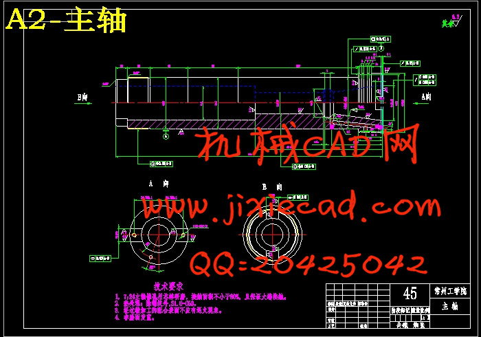
4.2主轴的设计要求 ……………………………………………………………… 15
4.2.1 主轴的主要尺寸参数 ………………………………………………… 16
4.2.2 主轴轴端结构 ………………………………………………………… 16
4.2.3 主轴的材料和热处理 ………………………………………………… 16
4.2.4 主轴主要精度指标 …………………………………………………… 17
4.3 主轴滚动轴承 ………………………………………………………………… 17
4.3.1 滚动轴承类型 ………………………………………………………… 17
4.3.2 主轴轴承配置与调整 ………………………………………………… 17
4.4主轴组件的设计计算 ………………………………………………………… 19
4.4.1 初选主轴直径 ………………………………………………………… 19
4.4.2 主轴悬伸量的确定 …………………………………………………… 19
4.4.3 主轴最佳跨距的选择 ………………………………………………… 19
4.5 主轴组件的校核计算 ………………………………………………………… 20
4.5.1 主轴组件的刚度计算 ………………………………………………… 20
4.5.2 主轴组件的强度计算 ………………………………………………… 21
4.5.3 轴承的校核计算 ……………………………………………………… 23
4.5.4 键的校核计算 ………………………………………………………… 25
4.6 主轴内部刀具自动夹紧机构及切屑清除装置 ……………………………… 26
4.7 主轴组件的润滑与密封 ……………………………………………………… 26
4.8 提高主轴组件性能的措施 …………………………………………………… 27
结论 ………………………………………………………………………………… 29
参考文献……………………………………………………………………………… 30
致谢…………………………………………………………………………………… 31